Piezoelectric combining jet device and its making process

A jet and piezoelectric technology, applied in the field of synthetic jet production, can solve the problems of low reliability and consistency, and achieve the effect of improving reliability and consistency

Inactive Publication Date: 2007-11-07
NORTHWESTERN POLYTECHNICAL UNIV
View PDF1 Cites 23 Cited by
  • Summary
  • Abstract
  • Description
  • Claims
  • Application Information

AI Technical Summary

Problems solved by technology

[0004] In order to overcome the problems of low reliability and low consistency caused by the bonding process in the prior art, the present invention provides a piezoelectric synthetic jet and its manufacturing method. The porous silicon layer is finally released to form a cavity, the nozzle is formed by inductively coupled plasma etching, the silicon vibration diaphragm is deposited by low-pressure chemical vapor deposition, and the piezoelectric film is prepared by the sol-gel method. The cavity, nozzle, vibration Diaphragm and piezo film are fabricated on the same silicon substrate for improved synthetic jet reliability and consistency

Method used


Image

  • Piezoelectric combining jet device and its making process
  • Piezoelectric combining jet device and its making process
  • Piezoelectric combining jet device and its making process

Examples


Embodiment Construction

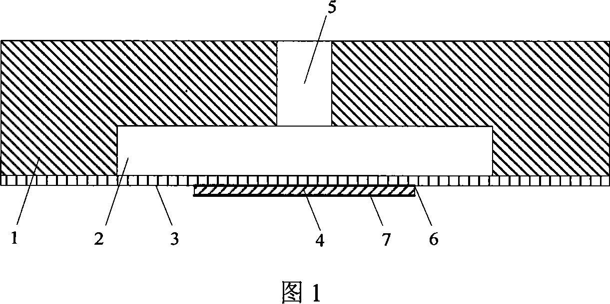
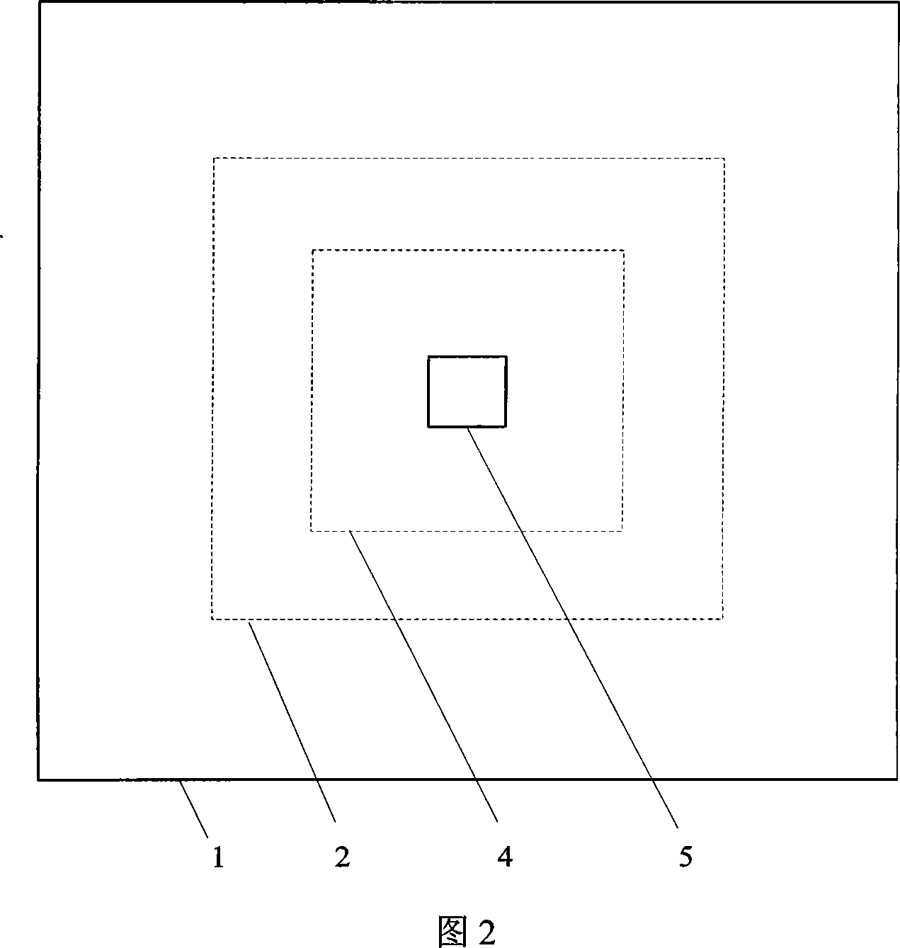
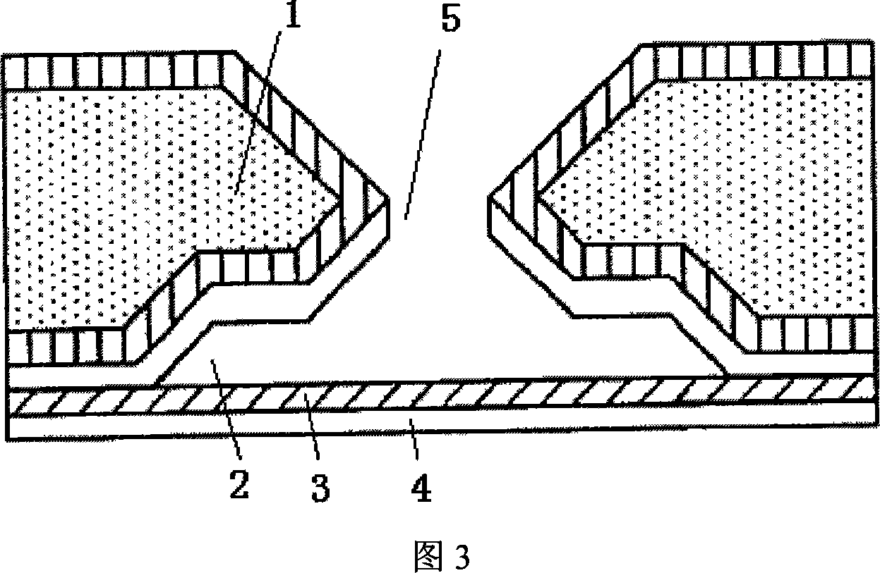
[0016] Refer to Figure 1 and Figure 2. The present invention includes a silicon substrate 1 , a cavity 2 , a spout 5 , a vibrating membrane 3 , a piezoelectric actuator 4 , an upper electrode 6 and a lower electrode 7 . Below the silicon substrate 1 is a cavity 2 with a square cross-section. Located above the cavity 2 and connected to the cavity 2 is a nozzle 5 with a square cross-section. The cavity 2 and the nozzle 5 run through the silicon substrate 1, and the nozzle 5 is connected to the cavity. 2 and the external flow field. The vibrating diaphragm 3 is made of polysilicon material, located on the lower surface of the silicon substrate 1 , and forms a suspended film below the cavity 2 . The piezoelectric actuator 4 is composed of a PZT piezoelectric ceramic material, and an upper electrode 6 and a lower electrode 7 attached to its upper and lower surfaces, and is located in the center of the lower surface of the vibrating diaphragm 3 . Wherein, the cross-sectional shape...


PUM


Abstract

The piezoelectric combining jet device includes a silicon base, a cavity, a jet, a vibrating membrane and a piezoelectric actuator. It features the piezoelectric actuator comprising piezoelectric material, and one upper electrode and one lower electrode adhered separately to the upper and lower surfaces of the piezoelectric material. The piezoelectric combining jet device is made through an electrochemical etching process, which includes preparing a porous silicon layer, releasing porous silicon to form cavity, inducing coupled plasma etching to form the jet, low pressure chemical vapor depositing the vibrating silicon diaphragm, and sol-gel process to prepare the piezoelectric film. The piezoelectric combining jet device with cavity, jet, vibrating silicon diaphragm and piezoelectric film prepared on the identical silicon base has high reliability and consistency.

Description

technical field [0001] The invention relates to a piezoelectric synthetic jet device and a manufacturing method of the synthetic jet device. Background technique [0002] Synthetic jet is one of the important devices in the field of flow control. It uses piezoelectric, electrostatic or electromagnetic driving methods to make its elastic diaphragm vibrate, thereby causing periodic changes in the volume of the cavity, thereby continuously moving the external gas The cavity is inhaled and discharged through the nozzle, and a synthetic jet is generated without an additional air source to achieve active control of the flow field. [0003] Refer to Figure 3. The document "US Patent No. US 6,457,654 Micromachined synthetic jet actuators and applications thereof" discloses a piezoelectric synthetic jet, which uses MEMS etching technology to process the cavity of the synthetic jet on a silicon wafer 2 and the nozzle 5 structure, and then assemble the vibrating diaphragm 3 and the p...

Claims


Application Information

Patent Timeline
Patent Type & Authority Applications(China)
IPC IPC(8): B05B17/04
Inventor 邓进军苑伟政马炳和朱业传
Owner NORTHWESTERN POLYTECHNICAL UNIV
Why Eureka
Try Eureka