Flat-plate antenna and packaging device and bushing device

A technology for packaging devices and antennas, which is applied to antennas, antenna arrays, antenna components and other directions, can solve the problems of poor production consistency, troublesome processes, and low production efficiency of FRP radomes, and achieves simple and fast assembly processes and overall manufacturing. The effect of cost reduction, high electrical performance consistency

Active Publication Date: 2011-06-08
COMBA TELECOM TECH (GUANGZHOU) CO LTD +1
View PDF0 Cites 0 Cited by
  • Summary
  • Abstract
  • Description
  • Claims
  • Application Information

AI Technical Summary

Problems solved by technology

[0005] In the prior art, the fixed sub-array is fastened with screws and nuts. This method is cumbersome, resulting in low production efficiency due to time-consuming, and due to the process, time-consuming, and many accessories, etc., it is also at the same time lead to higher cost
[0006] In addition, the current packaging method of the smart antenna is to use the overall package of the FRP radome. The biggest disadvantage of this packaging method is that the production consistency of the FRP radome is not good, resulting in a large difference in the consistency of each pair of antennas. Basically, each pair of antennas Independent debugging is required, which directly leads to low production efficiency of smart antennas, and even so, the consistency of each antenna may not be guaranteed

Method used


Image

  • Flat-plate antenna and packaging device and bushing device
  • Flat-plate antenna and packaging device and bushing device
  • Flat-plate antenna and packaging device and bushing device

Examples


Embodiment Construction

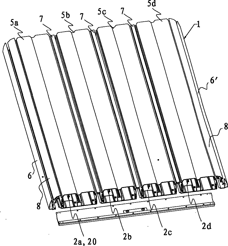
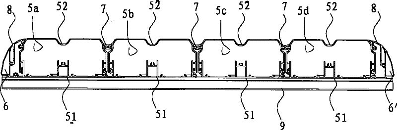
[0043] see figure 1 and figure 2 , the panel antenna of the present invention includes an antenna package device 1, radiation oscillator columns 2a-2d, a power division network (not shown), a calibration network (not shown) and a shielding box (not shown), and the antenna package device 1 is used for An installation platform is provided for the entire antenna. The radiation oscillator rows 2a-2d are formed by a single row of multiple radiation oscillators 20 arranged along the same longitudinal direction, and the radiation oscillators 20 of the same radiation oscillator row 2a-2d pass through The power dividing network (not shown) realizes parallel feeding, and multiple radiating oscillator columns 2a-2d form an antenna array. In the antenna array, the power dividing network (not shown) of each radiating oscillator column 2a-2d and the calibration network (not shown) are electrically connected, so that the signal calibration of the power dividing network (not shown) can be r...


PUM


Abstract

This invention discloses a flat antenna applying an antenna jacket device composed of a package device of multiple single antennas, which includes a base plate and a cover formed by two matched sections extending together, in which, said base plate includes a base board and side boards standing on either side of the surface of the base board as isolation strips, and internal plugged slots and ribs are set outside of the side boards, a first pair of vibrator slots extending along the lengthwise direction of the base plate is set on the surface of the base board for plugging radiation vibrator arrays, said cover includes a top plate and two side walls hanging down from two sides of the top plate and internal plugged ribs / slots matching to those of the two side plates of the base plate are set insides of the two side walls.

Description

technical field [0001] The invention relates to a flat panel antenna, and its corresponding packaging device and set device. Background technique [0002] Panel antennas are widely used in the field of mobile communications. The following takes the smart antenna of TD-SCDMA system as an example to illustrate some shortcomings of panel antennas. [0003] As one of the third generation mobile communication (3G) systems, TD-SCDMA has broad application prospects. As one of the key technologies of the TD-SCDMA system, the planar smart antenna has become a research hotspot in the antenna industry. In the TD-SCDMA system, the system performance can be improved by using the smart antenna. In a nutshell, smart antennas can increase coverage distance, reduce initial infrastructure costs, improve link performance, and increase system capacity. [0004] At present, the realization method of the smart antenna is to design several sub-arrays side by side in the horizontal direction of ...

Claims


Application Information

Patent Timeline
Patent Type & Authority Patents(China)
IPC IPC(8): H01Q1/00H01Q1/42H01Q3/00H01Q3/24H01Q3/26H01Q21/00
Inventor 游建军卜斌龙苏小兵赖展军
Owner COMBA TELECOM TECH (GUANGZHOU) CO LTD
Why Eureka
Try Eureka