Manufacturing method of resistor chip and photomask

A manufacturing method and photomask technology, applied in the field of semiconductor technology, can solve the problem that the consistency of electrical performance parameters of resistor chips cannot be guaranteed, etc.

Pending Publication Date: 2020-06-02
ZHUZHOU CRRC TIMES SEMICON CO LTD
View PDF0 Cites 0 Cited by
  • Summary
  • Abstract
  • Description
  • Claims
  • Application Information

AI Technical Summary

Problems solved by technology

[0008] In the existing process flow, due to the fluctuation of ion implantation process parameters, and the uniformity of the inside and between sheets of the furnace tube advancement process, the consistency of the electrical performance parameters of the final product of the above-mentioned resistor chips cannot be guaranteed.

Method used


Image

  • Manufacturing method of resistor chip and photomask
  • Manufacturing method of resistor chip and photomask
  • Manufacturing method of resistor chip and photomask

Examples


Embodiment Construction

[0070] The implementation of the present invention will be illustrated by specific specific examples below, and those skilled in the art can easily understand other advantages and effects of the present invention from the content disclosed in this specification. Although the description of the invention will be presented in conjunction with a preferred embodiment, it is not intended that the features of the invention be limited to that embodiment only. On the contrary, the purpose of introducing the invention in conjunction with the embodiments is to cover other options or modifications that may be extended based on the claims of the present invention. The following description contains numerous specific details in order to provide a thorough understanding of the present invention. The invention may also be practiced without these details. Also, some specific details will be omitted from the description in order to avoid obscuring or obscuring the gist of the present inventio...


PUM


Abstract

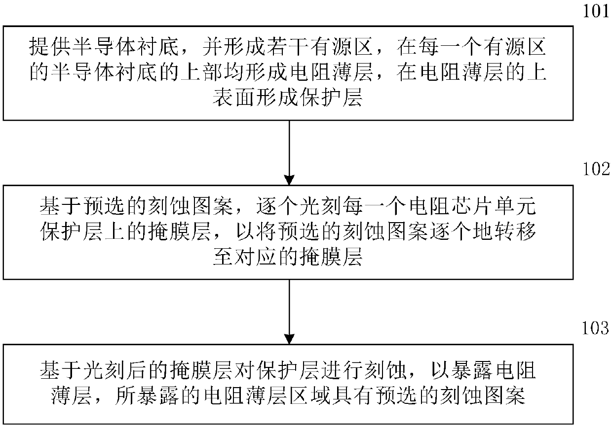
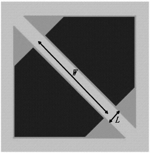
The invention belongs to the technical field of semiconductor processes, and particularly discloses a manufacturing method of a resistor chip and a photomask. The method comprises the following steps:providing a semiconductor substrate; photoetching the mask layer on each resistor chip unit protection layer one by one based on the pre-selected etching pattern so as to transfer the pre-selected etching pattern to the corresponding mask layer one by one; and etching the protective layer based on the photoetched mask layer to expose the resistance thin layer, the exposed resistance thin layer area having a pre-selected etching pattern, and the size of the etching pattern defining the actual resistance of the resistance chip unit. According to the invention, the consistency of the electricalperformance parameters of the semiconductor device can be ensured, and the semiconductor devices of the same production batch and different production batches can have the same electrical performanceparameter.

Description

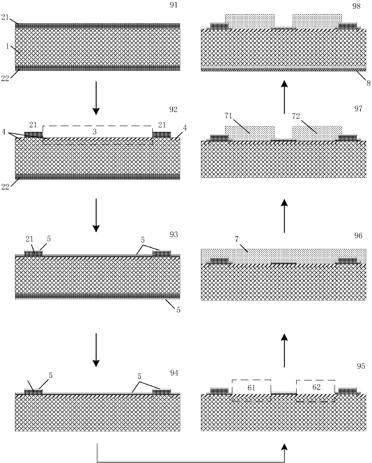
technical field [0001] The present invention relates to a semiconductor process, in particular to a semiconductor process for resistive chip manufacture. The invention specifically discloses a method for manufacturing a resistor chip and a photomask plate used in the above-mentioned manufacturing method. Background technique [0002] The existing manufacturing process of single crystal silicon diffused resistance adopts the technical scheme of ion-implanting P-type impurity on N-type substrate, and then forming P-type doped layer by furnace tube advancing process. [0003] The process flow of the manufacturing process of the above-mentioned single crystal silicon diffused resistance includes steps: [0004] First, ion-implant P-type impurities on the N-type substrate; [0005] Then, a P-type doped layer is formed by a furnace tube advancing process, and a protective layer is formed on the doped layer; [0006] Subsequently, holes are uniformly opened on the protective lay...

Claims


Application Information

Patent Timeline
IPC IPC(8): H01L21/02G03F1/62
CPCH01L28/20G03F1/62
Inventor 刘坤郑昌伟陈喜明赵艳黎周正东周维龚芷玉张文杰刘锐鸣李诚瞻
Owner ZHUZHOU CRRC TIMES SEMICON CO LTD
Why Eureka
Try Eureka