Hydraulically-driven fan for cooling tower

A hydrodynamic and cooling tower technology, applied in the direction of reaction engine, hydroelectric power generation, machine/engine, etc., can solve the problem of low energy conversion efficiency, achieve low vibration and noise of tower body, reduce vibration, and uniform force Effect

Inactive Publication Date: 2007-11-21
金先培 +1
View PDF1 Cites 8 Cited by
  • Summary
  • Abstract
  • Description
  • Claims
  • Application Information

AI Technical Summary

Problems solved by technology

[0003] The object of the present invention is to solve the problem of low energy conversion efficiency in the prior art, to provide a cooling tower hydrodynamic fan using a counter-action water turbine as a power source, thereby improving the utilization rate of the cooling tower’s hydrodynamic energy and achieving 100% energy saving. Improve the water flow distribution to one side to reduce the noise and vibration during operation

Method used


Image

  • Hydraulically-driven fan for cooling tower
  • Hydraulically-driven fan for cooling tower

Examples


Embodiment 1

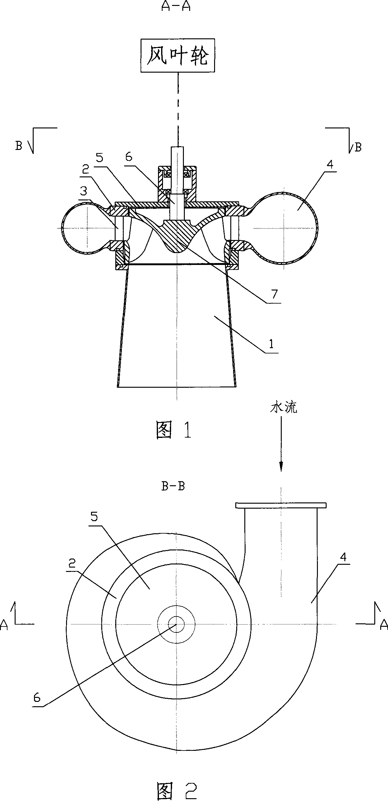
[0015] The device includes a wind impeller and a water turbine, the output shaft of the water turbine is connected with the rotating shaft of the wind impeller, and the water turbine is a reaction type water turbine, which includes a draft tube 1, and a seat ring 2 is fixedly connected to the upper end of the draft tube 1 , a water guide blade 3 is provided in the seat ring, a volute 4 is fixedly connected to the outer periphery of the seat ring 2, a cover plate 5 is provided on the upper surface of the seat ring 2, and a vertically inserted seat ring is installed at the center of the cover plate 5 through a bearing. The main shaft 6 in the center is equipped with a runner 7 of an impact water turbine at the lower end of the main shaft. The runner 7 can be installed in the axial flow turbine of the existing impact water turbine class according to the flow of water, the water head and the required efficiency and speed of the water turbine. Choose one of the runners of , Francis ...

Embodiment 2

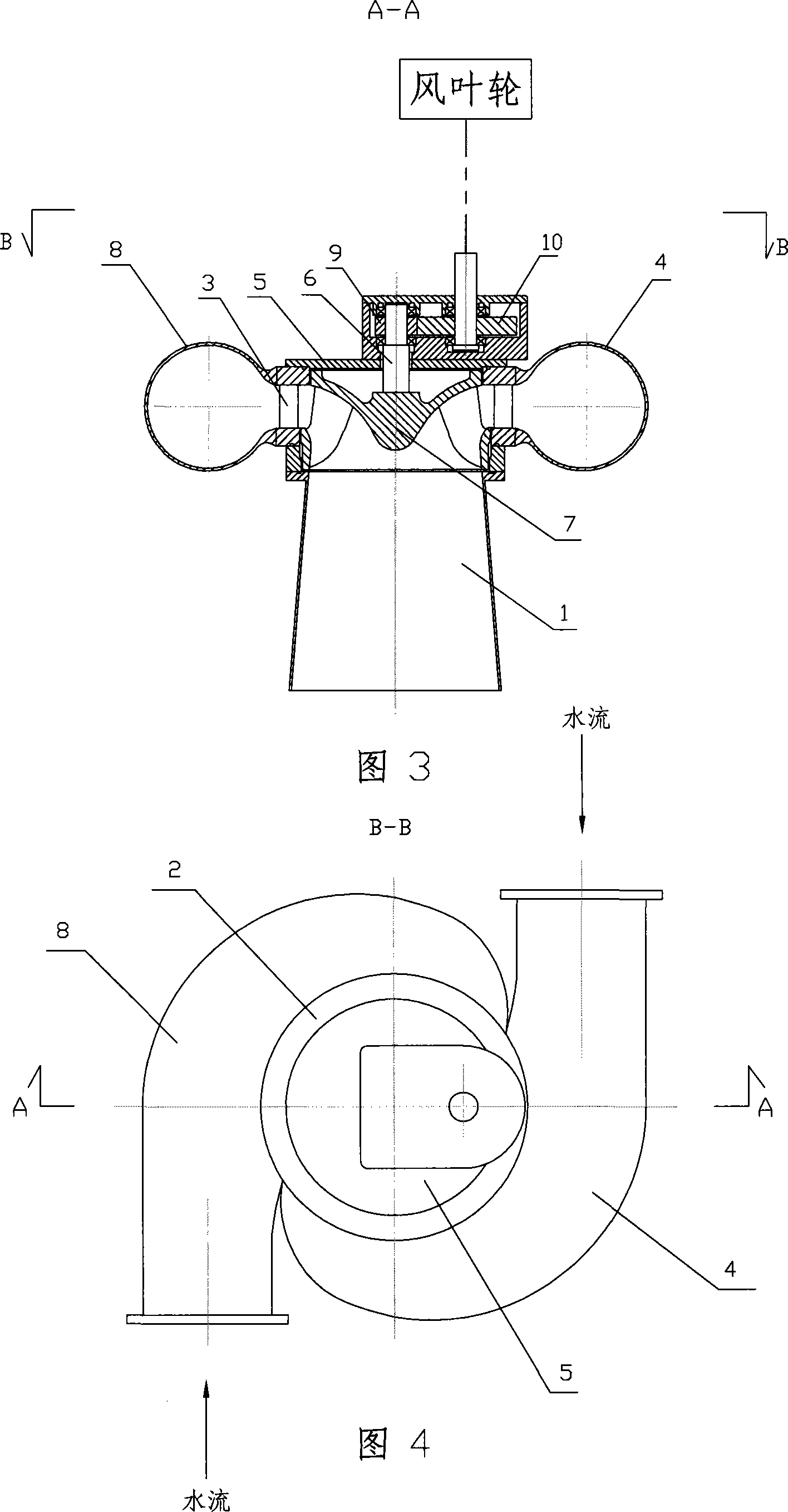
[0018] Referring to Figures 3 and 4, this example adds a volute 8 on the basis of Embodiment 1, that is to say, two volutes 4 and 8 are fixedly connected to the outer periphery of the seat ring 2, and the two volutes are connected with the seat ring 2 The axis is the axis and the axisymmetric reverse arrangement forms a bidirectional symmetrical water inlet distribution centered on the seat ring, as shown in Figure 4 . The two-way symmetrical water inlet distribution can make the runner 7 evenly stressed and rotate smoothly, greatly reducing the vibration of the water turbine, thereby minimizing the vibration and noise of the tower body during operation.

[0019] In addition, when the output speed of the water turbine can match the rated speed of the wind impeller, use the main shaft 6 of the water turbine to directly drive the wind impeller to rotate, as shown in Figure 1; when the two speeds cannot match, a gear governor can be used. For adjustment, as shown in Figure 3, wha...


PUM


Abstract

The invention is a cooling tower hydrodynamic fan. It is made of a vane wheel and a water turbine, the output axis of the water turbine is connected with the revolution axis of the vane wheel. This water turbine is a reaction-type wheel, including a tail water pipe 1, on top of which it is mounted a seating ring 2 with picket vanes 3 in the middle, volutes 4 & 8 around periphery and a cover plate 5 on the upper head plate. In the center of the cover plate 5 there is a backbone 6 inserting the center of seating ring 2 vertically with pillow. The runner 7 is loaded on the lower end of backbone 6. The utilization ratio of hydroenergy can be increased from 80% to 90%, higher than impulse wheel because of reaction-type structure. What is more is that its two-way symmetric inlet distribution can make the runner stressed homogeneously and decrease the vibration of water turbine , accordingly can decrease vibration and noise to the lowest level when running .

Description

technical field [0001] The invention relates to a cooling tower fan, in particular to a cooling tower hydrodynamic fan. Background technique [0002] In the prior art, the cooling towers of large-scale refrigeration air conditioners and industrial hot water generally use water pumps to send the hot water to be cooled to the tower, and then spray it down with a shower to exchange heat between the sprayed hot water and the air. And get cooled. In order to accelerate the heat exchange between hot water and air, a fan is often installed in the tower. Existing fans generally consist of a wind impeller, a motor and a reducer, and the motor drives the wind impeller to rotate through the reducer. Due to the high speed of the motor and the mechanical transmission of the reducer, the noise is large during operation and the tower vibrates. At the same time, the motor consumes a large amount of electric energy, which is not conducive to energy saving and environmental protection. In ...

Claims


Application Information

Patent Timeline
Patent Type & Authority Applications(China)
IPC IPC(8): F04D25/04F03B3/18
CPCY02E10/223Y02E10/20
Inventor 李大应金先培
Owner 金先培
Why Eureka
Try Eureka