Multi-edge composite cutting tools

A cutting tool and cutting edge technology, applied in the field of multi-edge combined cutting tools, can solve problems such as low cutting efficiency, and achieve the effects of improving cutting depth, diversifying materials, and changing processing forms.

Inactive Publication Date: 2007-11-28
上海美恩精密工具有限公司
View PDF0 Cites 12 Cited by
  • Summary
  • Abstract
  • Description
  • Claims
  • Application Information

AI Technical Summary

Problems solved by technology

[0004] The technical problem to be solved by the present invention is to provide a high-efficiency multi-edge Combined Cutting Tool

Method used


Image

  • Multi-edge composite cutting tools
  • Multi-edge composite cutting tools
  • Multi-edge composite cutting tools

Examples


Embodiment Construction

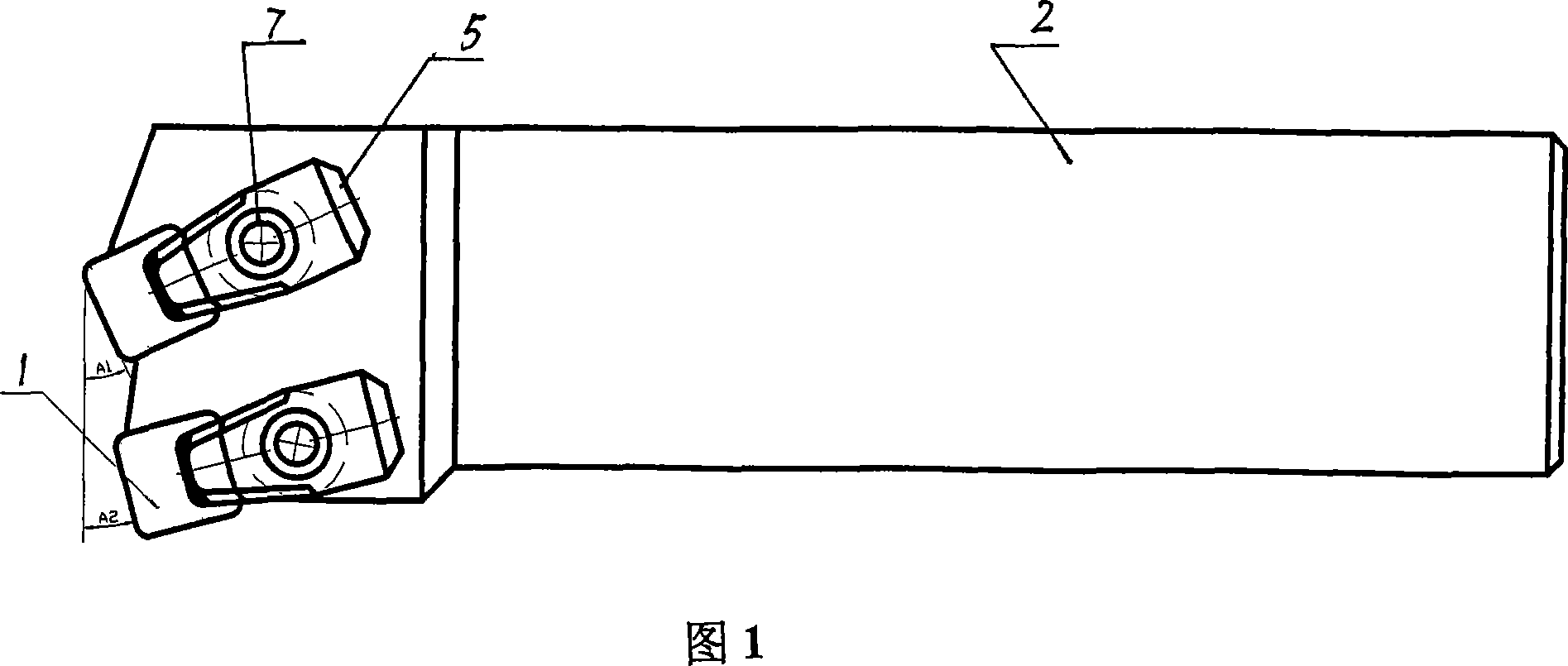
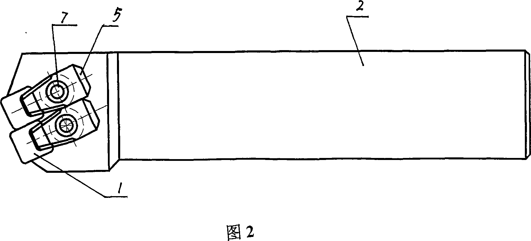
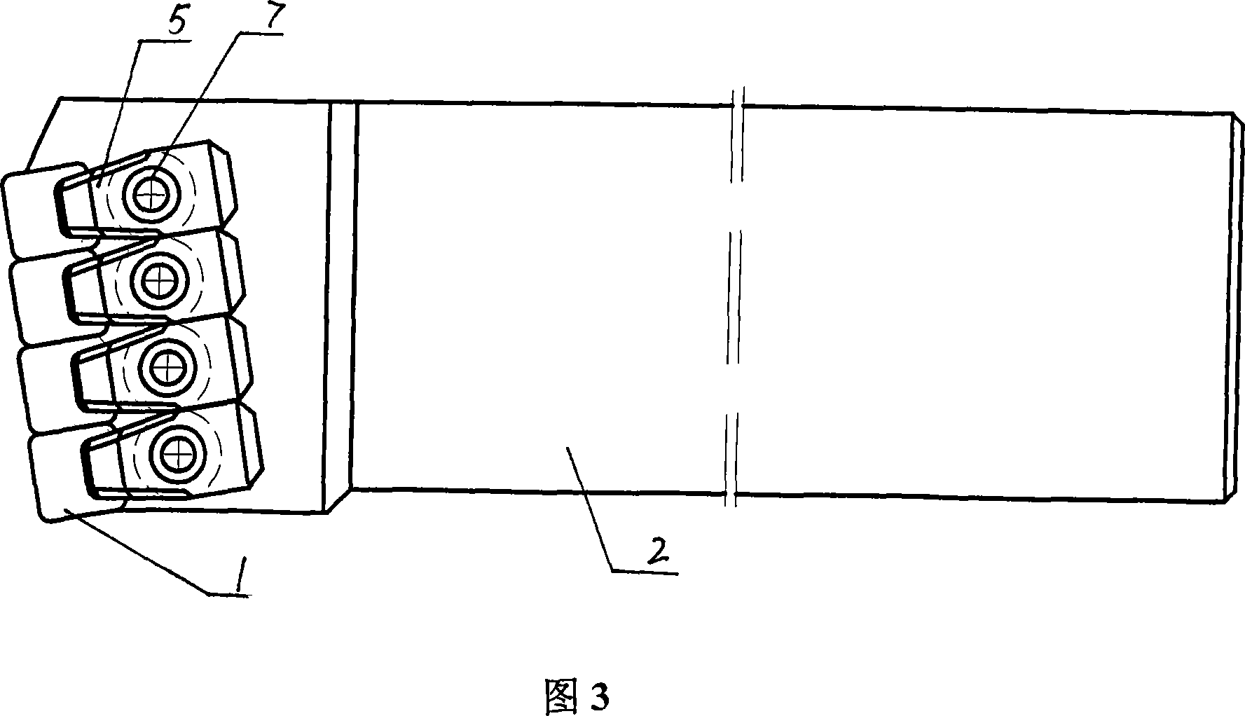
[0030] Below in conjunction with Fig. 1-Fig. 4, the present invention is described in further detail as follows:

[0031] A multi-cutting-edge combined cutting tool includes a cutter bar 2, and more than one blade mounting mechanism is arranged at the front end of the cutter rod 2, and blades 1 are respectively arranged on the blade mounting mechanism.

[0032] The blade mounting mechanism is as follows: a blade mounting groove 8 is set at the front end of the knife bar 2, a groove 9 is established behind the blade mounting groove 8, a knife pad 3 is placed at the bottom of the blade mounting groove 8, and a blade 1 is arranged on the knife pad 3. The bottom of the T-shaped pressing plate 5 is embedded in the groove 9 , the front end of the T-shaped pressing plate 5 presses the blade 1 tightly, and the pressing plate screw 7 fixes the T-shaped pressing plate 5 on the cutter bar 2 .

[0033] In order to achieve linkage between the T-shaped pressure plate 5 and the pressure plat...


PUM


Abstract

The combined cutting tool with several cutting edges includes one cutter bar, and several cutting blade mounting mechanisms with separately mounted blades in the same or different entering angles. On the one hand, the combined cutting tool with several cutting edges can cut with its multiple cutting edges in doubled cutting depth, increased feed and doubled cutting efficiency. On the other hand, the present invention has flexible machining form, convenient operation, changeable number of cutting edges and adjustable entering angles. In addition, the cutting blades may be made of different materials, cubic boron nitride, diamond, hard alloy, etc. selected based on the machining requirement, machining cost and other factors.

Description

technical field [0001] The invention relates to a cutting tool, in particular to a multi-edge combined cutting tool. Background technique [0002] Ordinary cutting tools generally have a blade mounting mechanism and a cutting edge. With the development of modern metal rolling technology, a large number of high-hardness materials such as high-nickel-chromium, high-chromium-iron, and cast high-speed steel are widely used, which limits the application range and cutting efficiency of ordinary single-edged tools, especially in heavy-duty In the field of cutting processing, machine tools for heavy-duty cutting generally have good rigidity and high power. Due to the small size of the blade and few cutting edges, the choice of cutting depth is limited, so that the resources of high power and high rigidity of the machine tool cannot be used. Low cutting efficiency in heavy-duty machining applications of high-hardness materials such as high-nickel-chromium, high-chromium-iron, and ca...

Claims


Application Information

Patent Timeline
Patent Type & Authority Applications(China)
IPC IPC(8): B23B27/00B23B27/16
Inventor 李和鑫张太和
Owner 上海美恩精密工具有限公司
Why Eureka
Try Eureka