Steel box beam erection method for self-anchored suspension bridge

A technology for self-anchored suspension bridges and steel box girders, applied in bridge construction, bridges, erection/assembly of bridges, etc., can solve the problems that are not suitable for the erection of self-anchored suspension bridges, the safety of river navigation is greatly affected, and the technical limitations of steel box girder erection and other problems to achieve the effect of overcoming local instability, increasing stiffness and reducing compressive stress

Inactive Publication Date: 2007-11-28
HUNAN PROVINCIAL COMM PLANNING SURVEY & DESIGN INST CO LTD
View PDF0 Cites 28 Cited by
  • Summary
  • Abstract
  • Description
  • Claims
  • Application Information

AI Technical Summary

Problems solved by technology

[0007] For a bridge with a steel box girder structure, if it crosses a busy river with a high shipping grade, the erection process of the steel box girder will be greatly restricted
First of all, due to the busy shipping in the river, it is not feasible to directly assemble the frame of the steel box girder by erecting construction supports; secondly, due to the lack of large-scale transportation and lifting equipment in China, it is not suitable to close the river with heavy shipping, so the overall hoisting of temporary piers is used. There are also obstacles in the erection of steel box girders by the splicing method; while the cable-stayed cantilever assembly method needs to lift the steel box girders from the beam

Method used


Image

  • Steel box beam erection method for self-anchored suspension bridge
  • Steel box beam erection method for self-anchored suspension bridge
  • Steel box beam erection method for self-anchored suspension bridge

Examples


Embodiment Construction

[0033] The present invention will be described in further detail below in conjunction with the accompanying drawings and specific embodiments.

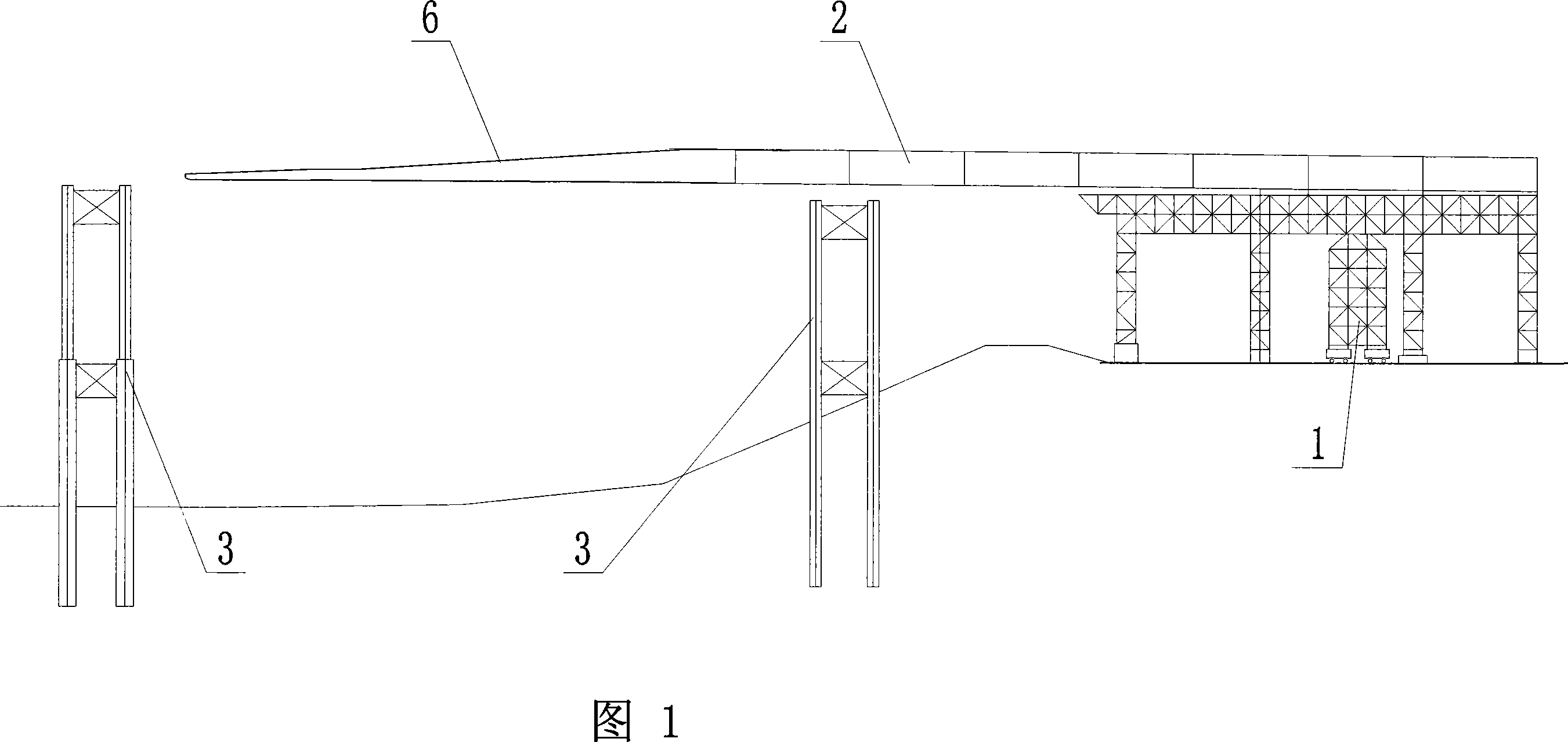
[0034] As shown in Figure 1, the steel box girder erecting method that the present invention is applied to self-anchored suspension bridge, its steps are:

[0035] (1), set steel box girder support 1 on the shore or non-navigation area, and carry out segmental pre-assembly of steel box girder 2 on steel box girder support 1;

[0036] (2) Temporary piers 3 of steel box girders meeting the waterway level are set in the river channel crossed by the suspension bridge;

[0037] (3) Push the pre-assembled steel box girder 2 forward by pushing or dragging, so that the steel box girder 2 is moved from the steel box girder bracket 1 to the steel box girder temporary pier 3, and the steel box girder is used to temporarily Pier 3 support; then continue to pre-assemble the steel box girder 2 in sections, push or drag continuously, so that the st...


PUM


Abstract

The invention discloses a method for steel-box beam erection applied in self-anchored suspension bridge. Procedures comprise that (1) the support for steel-box beam is set on bank or in no-navigation area and steel-box beam is preassembled with dividing segments on the support for steel-box beam; (2) temporary piers for steel-box beam, which satisfy waterway grade, are set in the waterway suspended by the suspension bridge; (3)preassembled steel-box beam is pushed forwards by pushing or dragging method so that the steel-box beam moves to temporary piers for steel-box beam from the support for steel-box beam and the steel-box beam is supported by temporary piers; then the steel-box beam is preassembled in dividing segments and it is pushed or dragged continuously so that preassembled steel-box beam moves forwards and it passes through temporary piers for steel-box beam on waterway in turn to achieve the opposite bank. The invention is provided with simple construction and it can be applied in waterway with busy suspension and higher waterway grade.

Description

technical field [0001] The invention belongs to the field of bridge engineering, in particular to a method for erecting a steel box girder applied to a self-anchored suspension bridge. Background technique [0002] With the development of the national economy and the advancement of bridge construction technology, the performance of steel used in domestic bridge structures has improved. Since the weight of steel box girders is lighter than that of concrete beams, steel box girders are also used in the construction of domestic long-span cable-stayed bridges and suspension bridges. more and more. With the further improvement of urban road network construction, more and more bridge types with better landscape effects are adopted, such as self-anchored suspension bridges, arch bridges, and low-tower cable-stayed bridges. The erection methods of steel box girders vary according to the structure of the bridge, the terrain conditions of the bridge site, the shipping conditions, and...

Claims


Application Information

Patent Timeline
IPC IPC(8): E01D21/00
Inventor 胡建华向建军刘榕杨沪湘王甜戴小冬
Owner HUNAN PROVINCIAL COMM PLANNING SURVEY & DESIGN INST CO LTD
Why Eureka
Try Eureka