Flow field visualization method and device
A visualization and flow field technology, applied in the direction of measuring devices, particle motion records, instruments, etc., can solve problems such as residual errors, high prices, and affecting the accuracy of results, and achieve the effect of reducing system costs
- Summary
- Abstract
- Description
- Claims
- Application Information
AI Technical Summary
Problems solved by technology
Method used
Image

Examples
Embodiment 1
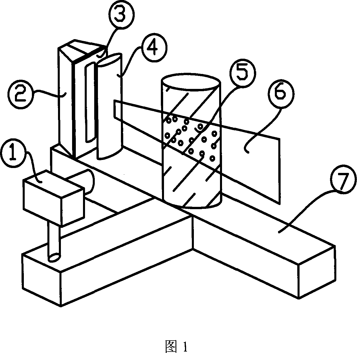
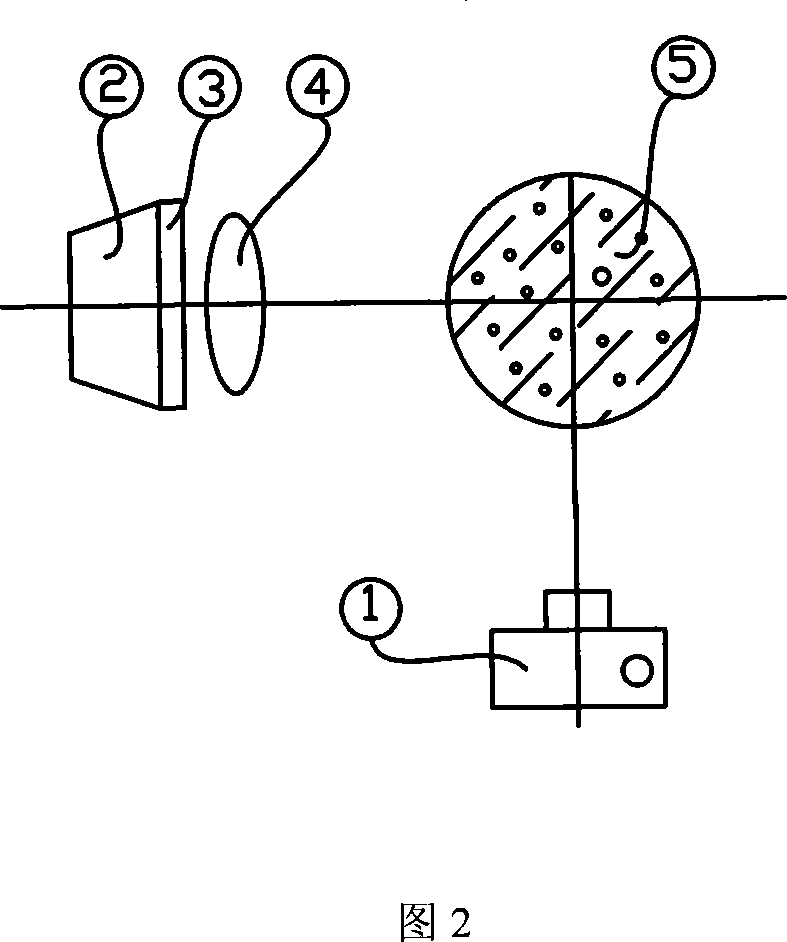
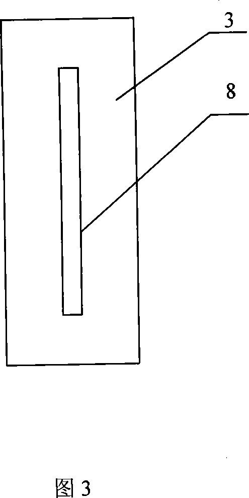
[0021] The visualization system consists of 1 camera, 2 light sources, 3 shading plates, 8 light transmission slots, 4 condenser mirrors, 5 particle containers, the observed fluid and display particles, and an installation platform 7. The installation structure is shown in Figure 1. The light source 2, the condenser lens 4 and the camera 1 can move on the platform 7 so as to obtain the best lighting and imaging effect. The display particles are mixed evenly by 80g206 polystyrene, 10g nylon and 10g fluorescent powder, heated at 210°C to fully fuse, and then granulated by a granulator after fusion, the particle diameter is 0.8mm, and the density is 1.05g / cm 3 . The fluid medium is water, and edible salt is added to adjust the density to 1.05g / cm 3 . The fluid is contained in a glass beaker with a diameter of 120mm and a height of 160mm. Add shading plate 3 in front of ultraviolet light source 2, and long 80mm is arranged on the shading plate 3, wide 2mm light-transmitting gro...
Embodiment 2
[0023] The visualization system of this embodiment is composed of 1 camera, 2 light sources, 3 light-shielding plates, 8 light-transmitting slots, 4 condenser mirrors, 5 particle containers, the observed fluid, display particles, and an installation platform 7. The installation structure is shown in Figure 1 . The light source 2, the condenser lens 4 and the camera 1 can move on the platform 7 so as to obtain the best lighting and imaging effects. The display particles are mixed evenly with 92g206 polystyrene, 5g atomic ash, and 3g infrared absorber, heated at 220°C to fully fuse, and then granulated by a granulator after fusion, with a particle diameter of 1.0mm and a density of 1.08g / cm 3 . The fluid medium is water, and edible salt is added to adjust the density to 1.08g / cm 3 . The fluid is filled with particle containers 5 with a diameter of 120 mm and a height of 160 mm. Add shading plate 3 in front of infrared light source 2, and long 80mm is arranged on the shading ...
Embodiment 3
[0025] The visualization system of this embodiment is composed of 1 camera, 2 light sources, 3 light-shielding plates, 8 light-transmitting slots, 4 condenser mirrors, 5 particle containers, the observed fluid, display particles, and an installation platform 7. The installation structure is shown in Figure 1 . The light source 2, the condenser lens 4 and the camera 1 can move on the platform 7 so as to obtain the best lighting and imaging effects. The display particles are mixed evenly by 85g206 polystyrene, 7g atomic ash, and 5g infrared absorber, heated at 230°C to fully fuse, and then granulated by a granulator after fusion, with a particle diameter of 1.2mm and a density of 1.08g / cm 3 . The fluid medium is water, and edible salt is added to adjust the density to 1.08g / cm 3 . The fluid is filled with particle containers 5 with a diameter of 120 mm and a height of 160 mm. Add shading plate 3 in front of ultraviolet light source 2, and long 80mm is arranged on the shading...
PUM
| Property | Measurement | Unit |
|---|---|---|
| Diameter | aaaaa | aaaaa |
| Density | aaaaa | aaaaa |
Abstract
Description
Claims
Application Information
 - Generate Ideas
- Intellectual Property
- Life Sciences
- Materials
- Tech Scout
- Unparalleled Data Quality
- Higher Quality Content
- 60% Fewer Hallucinations
Browse by: Latest US Patents, China's latest patents, Technical Efficacy Thesaurus, Application Domain, Technology Topic, Popular Technical Reports.
© 2025 PatSnap. All rights reserved.Legal|Privacy policy|Modern Slavery Act Transparency Statement|Sitemap|About US| Contact US: help@patsnap.com