Lighting device

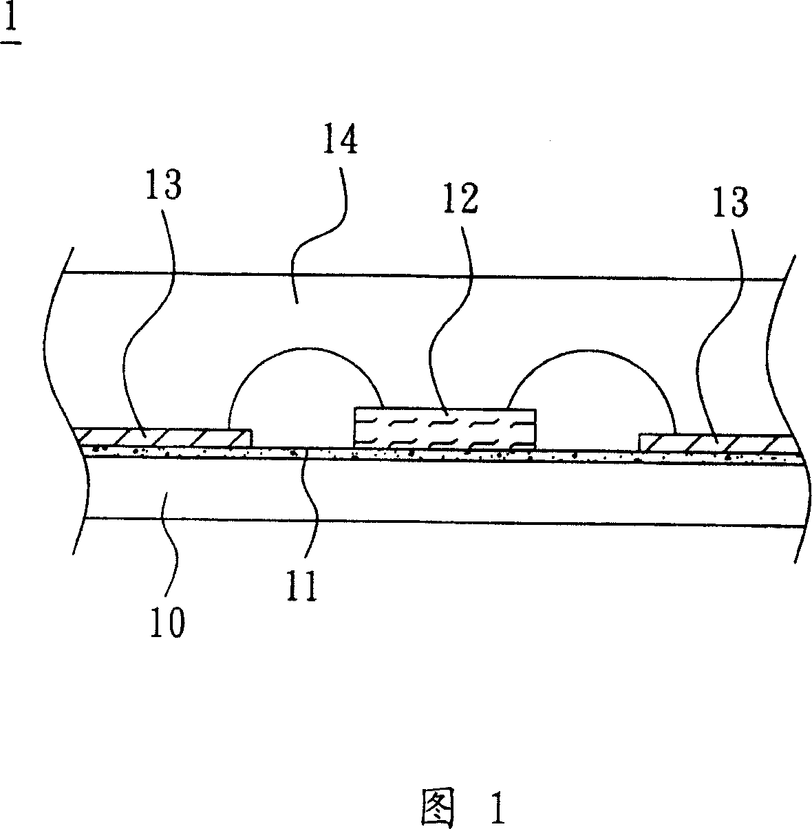
A light-emitting device and light-emitting element technology, which is applied in the direction of lasers, phonon exciters, laser components, etc., can solve the problems of light-emitting elements 12 that heat energy is difficult to dissipate, heat dissipation is not good, and the efficiency of light emission cannot be effectively improved. Heat dissipation performance and product reliability, avoiding thermal resistance and aging problems, reducing production cost and time

Inactive Publication Date: 2007-11-28
DELTA ELECTRONICS INC
View PDF0 Cites 4 Cited by
  • Summary
  • Abstract
  • Description
  • Claims
  • Application Information

AI Technical Summary

Problems solved by technology

[0004] The conventional LED light emitting device 1 only provides a light emitting effect, and part of the light emitted by the LED light emitting element 12 leaks from the side, and is not fully applied to a concentrated light emitting surface, and its luminous efficiency has not been effectively improved. , with the development of high efficiency and high brightness of the light-emitting device 1, the light-emitting element 12 will emit heat during operation, and the accumulated heat will increase the temperature and cause adverse effects on the luminous efficiency and service life of the light-emitting element 12
However, the conventional light-emitting element 12 is disposed on the insulating layer 11 with poor heat dissipation, and the airtight packaging of the encapsulation layer 14 makes it difficult for the heat emitted by the light-emitting element 12 to dissipate, so the problem of difficult heat dissipation becomes more obvious.

Method used


Image

  • Lighting device
  • Lighting device
  • Lighting device

Examples


Embodiment Construction

[0034] A light emitting device according to a preferred embodiment of the present invention will be described below with reference to related drawings, wherein the same elements will be described with the same reference symbols.

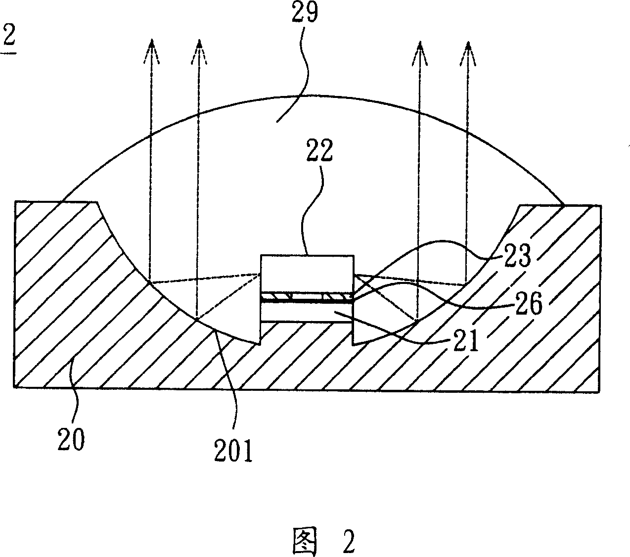
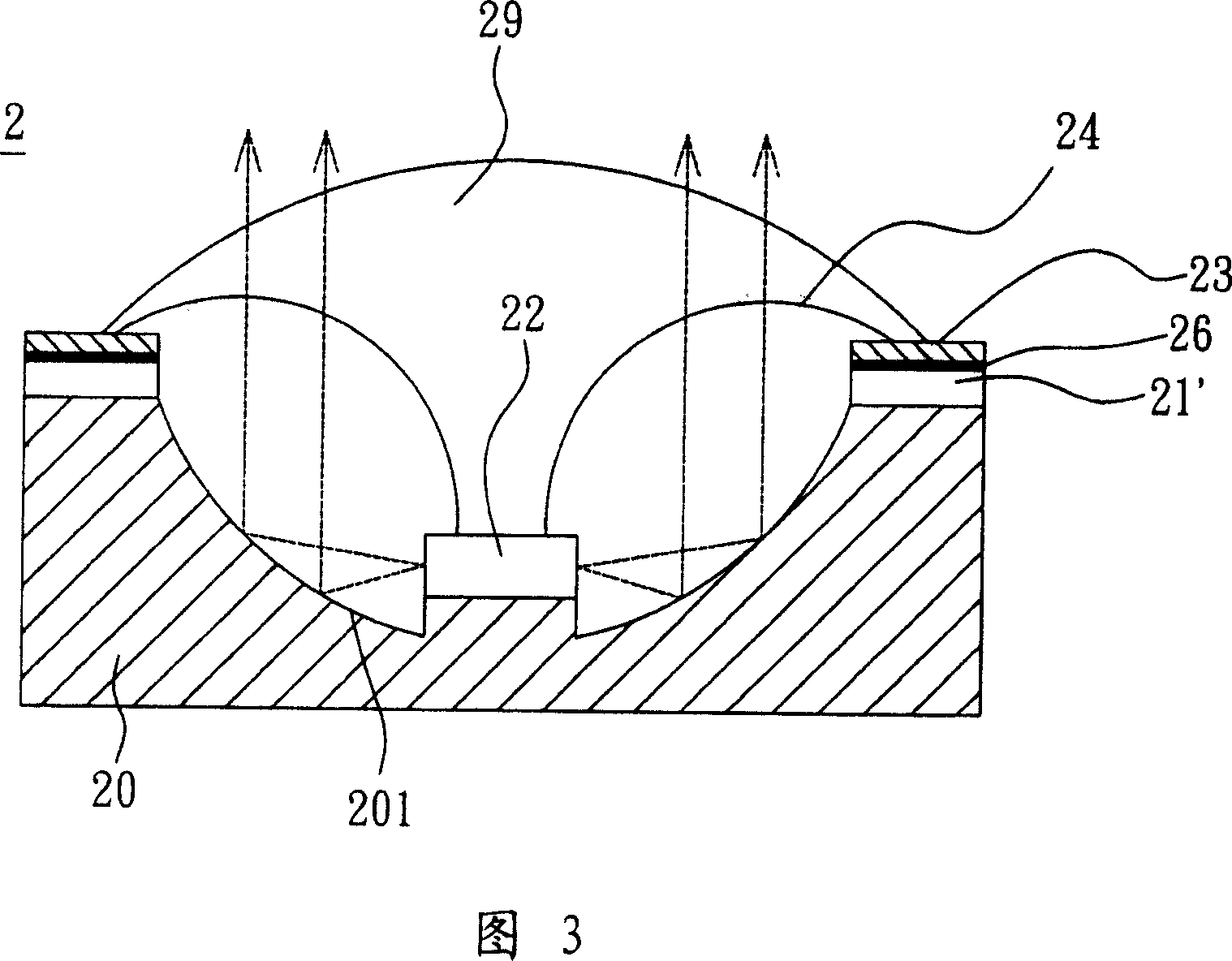
[0035] Referring to FIG. 2, a light emitting device 2 according to a preferred embodiment of the present invention includes a substrate 20, a first insulating layer 21, a connection layer 26, a metal layer 23, at least one light emitting element 22 and a protective layer. 29.

[0036] In this embodiment, the material of the substrate 20 can be made of at least one of copper, aluminum, magnesium, titanium and alloys thereof to provide better thermal conductivity; in addition, the material of the substrate 20 can also be made of ceramic materials , to provide better thermal conductivity, wherein, the surface of the substrate 20 has a structure 201 for improving light extraction efficiency.

[0037] In this embodiment, the first insulating layer 21 is ...


PUM


Abstract

The invention discloses a luminous device, which comprises the following parts: base, at least one luminous element and protective layer, wherein the base has a structure to elevate the luminous efficiency on the surface; the luminous element lies on the preset position of base with ray reflected, gathered and emitted to improve the emitting efficiency, which improves the luminous efficiency of luminous device.

Description

technical field [0001] The invention relates to a light emitting device, in particular to a light emitting device with good heat dissipation performance. Background technique [0002] With the development of the optoelectronic industry, light-emitting elements such as light-emitting diodes (LEDs) have been widely used in display applications of various electronic products. [0003] Please refer to FIG. 1, a conventional LED light emitting device 1 is provided with an insulating layer 11 on a substrate 10, and a plurality of LED light emitting elements 12 are arranged on the insulating layer 11, and then connected to the insulating layer 11 by wire bonding. A metal layer 13 on the insulating layer 11 forms an electrical connection, and finally the LED light-emitting elements 12 are covered with an encapsulation layer 14 to protect the light-emitting elements 12 from being damaged by mechanical, heat, moisture or other factors. [0004] The conventional LED light emitting dev...

Claims


Application Information

Patent Timeline
Patent Type & Authority Applications(China)
IPC IPC(8): H01L33/00H01L51/50H01L23/488H01L23/28H01S5/00H01L33/48
CPCH01L2224/48247H01L2224/48091H01L2924/0002
Inventor 张绍雄陈育川
Owner DELTA ELECTRONICS INC
Why Eureka
Try Eureka