Sealing cell

A technology for sealing batteries and sealing bodies, which can be used in batteries, secondary batteries, battery pack components, etc., and can solve problems such as decreased welding strength and poor welding.

Active Publication Date: 2007-11-28
MAXELL HLDG LTD
View PDF3 Cites 8 Cited by
  • Summary
  • Abstract
  • Description
  • Claims
  • Application Information

AI Technical Summary

Problems solved by technology

Therefore, similar to the above, welding defects such as gaps occur in

Method used


Image

  • Sealing cell
  • Sealing cell
  • Sealing cell

Examples


Embodiment Construction

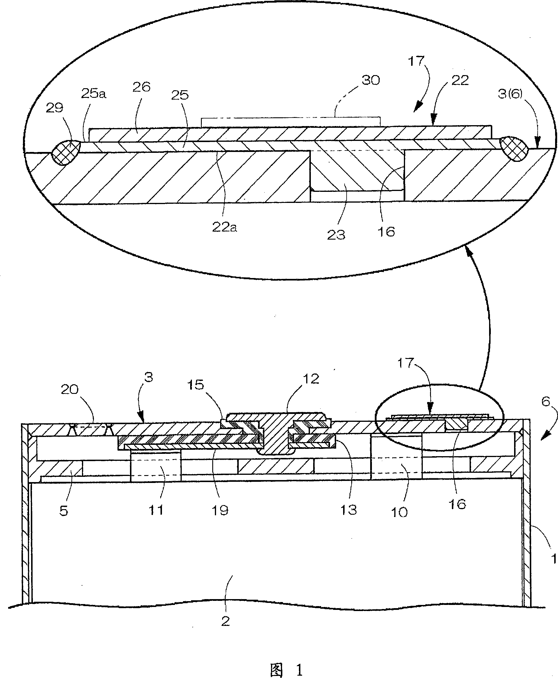
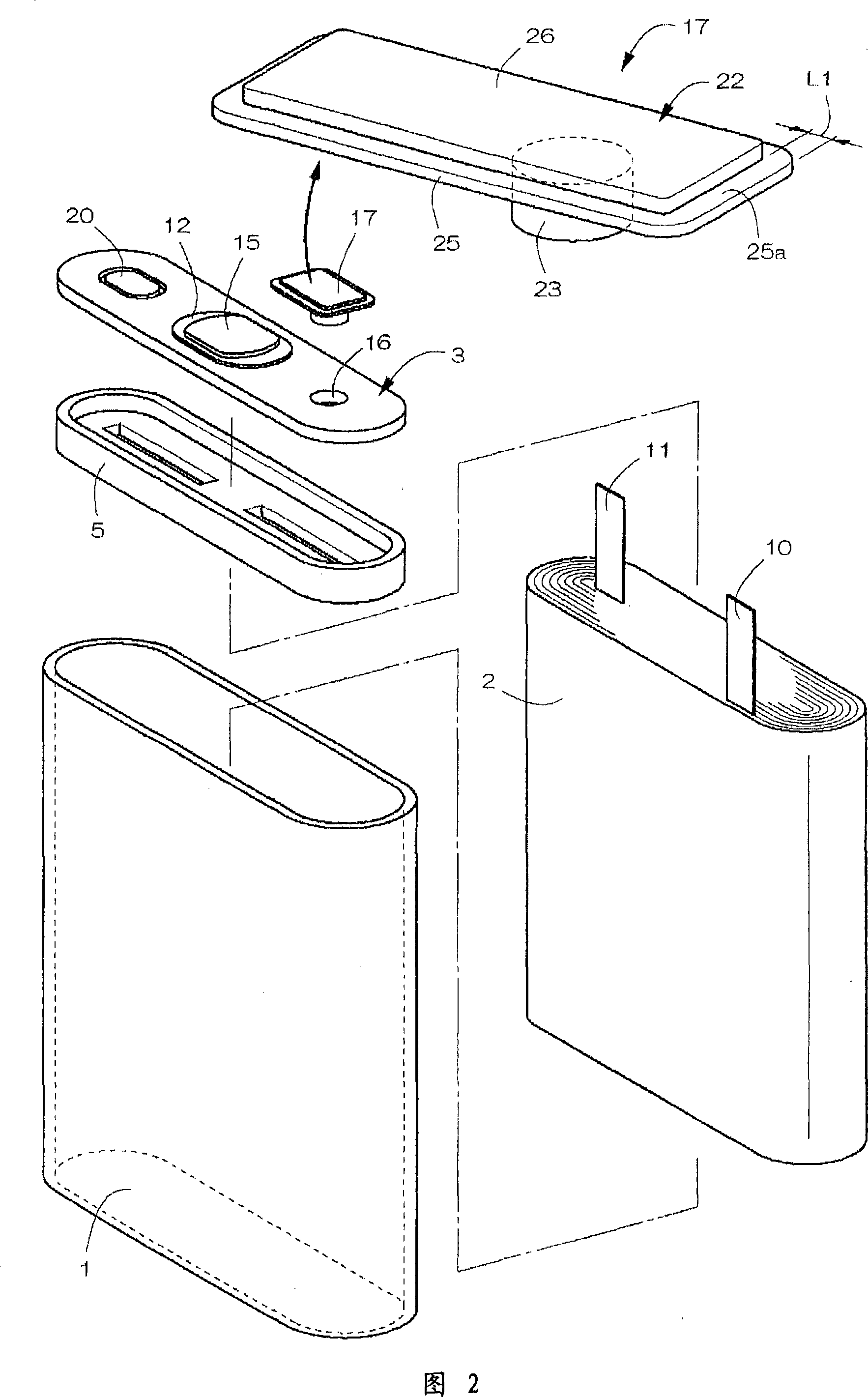
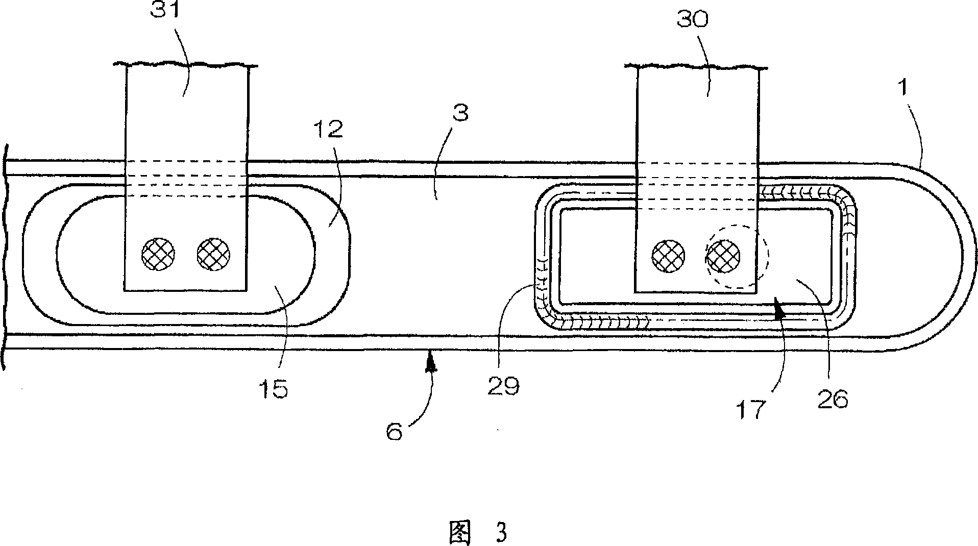
[0029] As shown in Figures 1 and 2, the sealed battery of the present invention includes: a bottomed square tube-shaped battery can 1 with left and right horizontal openings on the top; electrode body 2 and non-aqueous electrolyte contained in the battery can 1 ; a horizontally wide lid 3 that blocks and seals the upper surface of the opening of the battery can 1 ; and a plastic insulator 5 disposed inside the lid 3 . The left and right width of the battery can 1 is 34 mm, the vertical height is 46 mm, and the front and rear thickness is 4 mm. A battery case 6 is formed by the battery can 1 and the cover 3 .

[0030] As shown in FIG. 1 , the electrode body 2 is fabricated by being spirally wound with a strip-shaped separator interposed between a strip-shaped positive electrode and a strip-shaped negative electrode. The electrode body 2 has a flat shape as shown in FIG. 2 in a wound state. The positive electrode has a positive electrode active material layer containing a posi...


PUM


Abstract

To surely weld a sealing body to a battery case by reducing welding defects. After an electrolyte is injected into a battery case 6 from an electrolyte injection hole 16, the electrolyte injection hole 16 is closed by a sealing plug 17, and the sealing plug 17 is welded to a peripheral part of the electrolyte injection hole 16, whereby the electrolyte injection hole 16 is sealed. The sealing plug 17 is formed of a clad material formed by vertically joining an aluminum layer 25 to a nickel layer 26; the aluminum layer 25 is arranged on the battery case 6 side; and a peripheral part 25a of the aluminum layer 25 is projected to the outside of the sealing plug 17 relative to an edge of the nickel layer 26 and welded to a peripheral part of the electrolyte injection hole 16 by laser.

Description

technical field [0001] The present invention relates to sealed batteries such as lithium ion batteries. Background technique [0002] Patent Documents 1 to 3 disclose a sealed battery in which an electrode body, an electrolytic solution, and the like are accommodated in a battery can, and the upper surface opening of the battery can is closed with a cover to form a battery case. In this sealed battery, the electrolyte solution is injected into the battery can through a liquid injection hole provided on the cover, and then the liquid injection hole is blocked with a sealing body composed of a sealing plug or a plate, and then the liquid is sealed with a laser or the like. The sealing body is welded to the upper surface of the cap which is the peripheral portion of the liquid injection hole, so that the liquid injection hole is sealed with the sealing body. [0003] The sealed battery can be used as a power source to be mounted on external equipment such as a mobile phone or ...

Claims


Application Information

Patent Timeline
IPC IPC(8): H01M2/02H01M2/04H01M2/08H01M2/36H01M10/40
CPCY02E60/12Y02E60/10Y02P70/50H01M2220/30H01M50/183H01M50/169H01M50/308H01M10/0525
Inventor 渡边修杣友良树
Owner MAXELL HLDG LTD
Why Eureka
Try Eureka