Coil mutual-supplementary magnetic pass switching biconvex permanent magnetic motor

A magnetic flux switching, permanent magnet motor technology, applied in the shape/style/structure of winding conductors, magnetic circuit static parts, magnetic circuit rotating parts, etc., can solve the problem of increasing wire length and resistance, increasing air gap length, Increase the production process and other issues to achieve the effect of reducing resistance and copper loss, reducing end length, and improving cooling conditions

Inactive Publication Date: 2007-11-28
SOUTHEAST UNIV
View PDF0 Cites 19 Cited by
  • Summary
  • Abstract
  • Description
  • Claims
  • Application Information

AI Technical Summary

Problems solved by technology

However, placing permanent magnets on the rotor will cause a series of problems during the design and operation process, which are mainly reflected in the following three points: 1. For the structure of permanent magnets pasted on the surface of the rotor or inserted between the salient poles of the rotor, in order to To overcome the influence of centrifugal force generated by high-speed operation, it is usually necessary to make an auxiliary permanent magnet fixing device, and the permanent magnet is located between the stator and the rotor, which increases the length of the air gap, which not only increases the volume of the motor, but also leads to a weakening of the air gap magnetic density , affecting the output; 2. The embedded structure of the permanent magnet embedded in the rotor core will affect the mechanical strength of the rotor, and an auxiliary magnetic bridge is required, which wil

Method used


Image

  • Coil mutual-supplementary magnetic pass switching biconvex permanent magnetic motor

Examples


Embodiment Construction

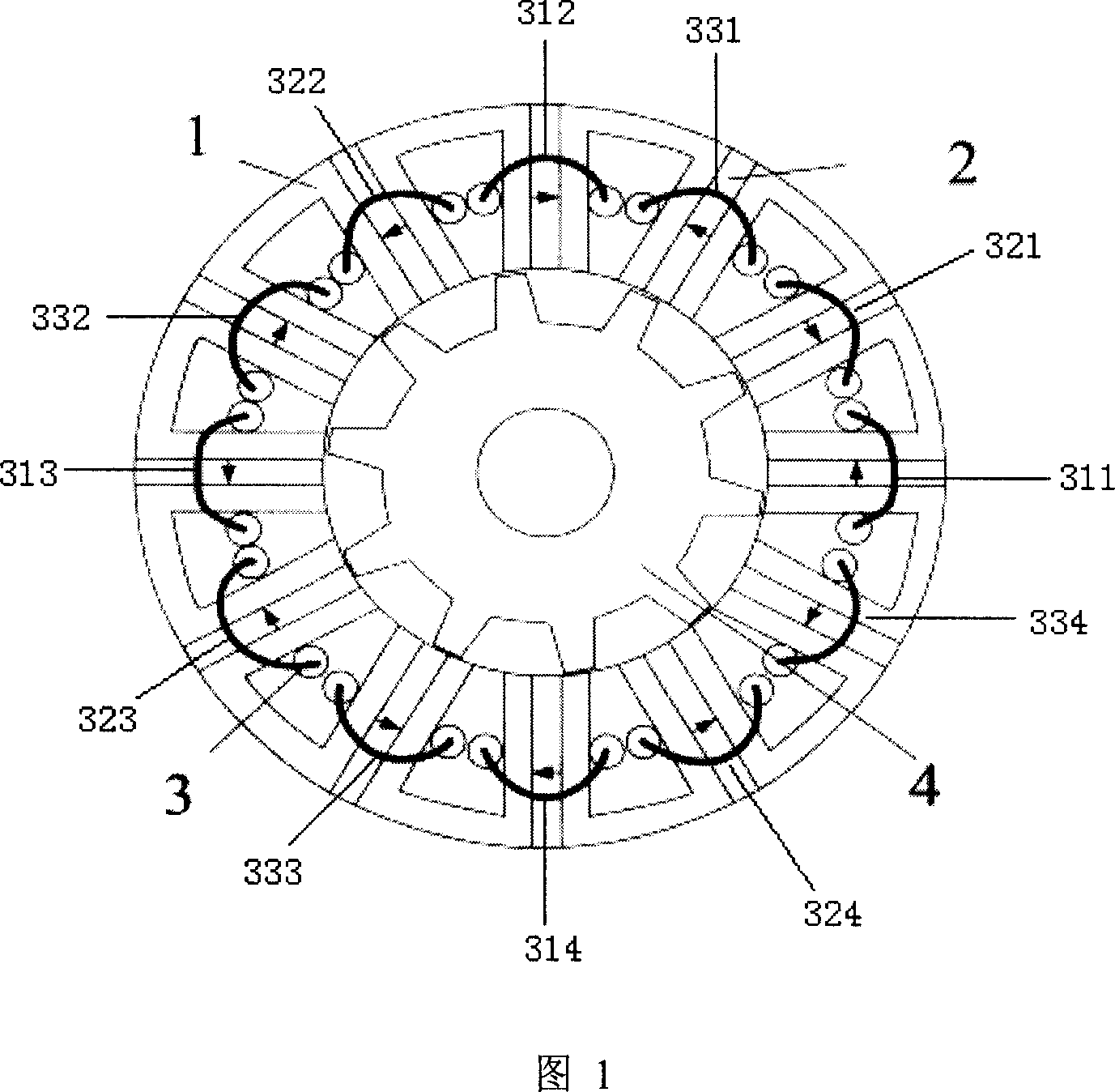
[0015] As shown in Figure 1, the double salient pole permanent magnet motor with complementary winding flux switching of the present invention includes a stator core 1 and a rotor core 4, the rotor 4 is located inside the stator 1, and both the stator 1 and the rotor 4 are double salient pole structures, wherein The stator core part is composed of 12 U-shaped magnetic cores, and the stator 1 is provided with a three-phase concentrated winding 3 and 12 permanent magnets 2;

[0016] The A-phase first winding coil 311 and the third winding coil 313 of the concentrated winding 3 are diametrically opposite, the second winding coil 312 and the fourth winding coil 314 are diametrically opposite, and each winding coil is sleeved in two adjacent winding coils in the stator 1 In the slot of the U-shaped iron core, and the above four winding coils are sequentially connected end to end in series; a permanent magnet 2 is arranged between two adjacent U-shaped magnetic conducting cores in th...


PUM


Abstract

The invention discloses a motor with stronger torque output ability and higher power density, which consists of stator (1) and rotor (4), wherein the rotor (4) lies in the interior or exterior of the stator (1); the stator (1) and rotor (4) are double-salient pole structures with the gathered winding (3) and permanent magnet (2) on the stator (1); the radial of second and fourth winding coils are faced with each gathered winding coil in the U-shaped magnetic iron groove of two adjacent stators (1); four winding coils connect front head to end sequently; the permanent magnet (2) is set between two adjacent U-shaped magnetic iron core.

Description

technical field [0001] The invention is a motor with simple and strong structure, strong torque output capability and high power density, and relates to the technical field of motor manufacturing. Background technique [0002] As the country with the largest reserves of rare earth materials in the world, our country vigorously researches and promotes the application of various new permanent magnet motors represented by rare earth permanent magnet motors, which has important theoretical significance and application value. Regardless of power generation or electric operation, new permanent magnet motors with high efficiency, high torque (power) density and low loss are showing a trend of accelerated development. Over the past decade or so, research hotspots have been focused on rotor permanent magnet motors represented by surface-mounted, plug-in and built-in types. However, placing permanent magnets on the rotor will cause a series of problems during the design and operation...

Claims


Application Information

Patent Timeline
IPC IPC(8): H02K1/17H02K1/14H02K1/24H02K3/18
Inventor 花为程明
Owner SOUTHEAST UNIV
Why Eureka
Try Eureka