Circular shielding insulating bus and machining method thereof

A technology of shielding insulation and bus bar, applied in the direction of insulating cables, insulating conductors, conductor/cable insulation, etc., can solve the problems of bringing in impurities, reducing the electrical insulation performance of the pipe mother, and the impossibility of matching humidity and temperature. The effects of increasing distance, improving power supply efficiency, excellent electrical performance and chemical stability

Active Publication Date: 2013-10-23
JIANGSU SHILIN ELECTRIC EQUIP
View PDF6 Cites 11 Cited by
  • Summary
  • Abstract
  • Description
  • Claims
  • Application Information

AI Technical Summary

Problems solved by technology

The disadvantage of the insulated busbar is mainly the insulation treatment of the intermediate connection. The insulation of the single pipe mother is done before leaving the factory. The intermediate joint is used for the docking of the single pipe mother and the single pipe mother on site. Insulation treatment of joints, but the humidity and temperature of the surrounding environment are impossible to match, and even impurities may be brought in when wrapping by hand, which greatly reduces the electrical insulation performance of the tube mother

Method used


Image

  • Circular shielding insulating bus and machining method thereof
  • Circular shielding insulating bus and machining method thereof

Examples


example 1

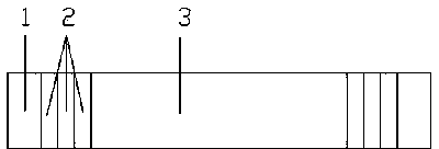
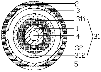
[0037] As shown in the figure, a 10KV circular shielded insulated bus bar includes a circular conductor 1 and an outer sheath 2. A circular channel 4 is provided in the circular conductor 1. The surface of the conductor is tightly wrapped with a layer of insulating shielding layer 3, where the insulating shielding layer 3 is composed of an insulating layer 31 and a shielding layer 32. The insulating layer 31 includes two layers of PTFE 311 and a heat shrinkable sheath 312 from the inside to the outside. Silicone oil is evenly coated between the tetrafluoroethylene 311 and the heat shrinkable sheath 312. After that, leave 5cm at both ends of each insulating shielding layer 3 to make the second, third, and fourth insulating shielding layers. Use polyolefin polymer as the outer protective layer outside the fourth insulating shielding layer. Cover 2, and ground the braided copper mesh 5 around the fourth insulating shielding layer.

[0038] The production method is as follows:

[003...

example 2

[0044] As shown in the figure, a 35KV circular shielded insulated bus bar includes a circular conductor 1 and an outer sheath 2. A circular channel 4 is provided in the circular conductor 1. The surface of the conductor is tightly wrapped with a layer of insulating shielding layer 3, where the insulating shielding layer 3 is composed of an insulating layer 31 and a shielding layer 32. The insulating layer 31 includes two layers of PTFE 311 and a heat shrinkable sheath 312 from the inside to the outside. Silicone oil is evenly coated between the tetrafluoroethylene 311 and the heat shrinkable sheath 312. After that, leave 5cm at both ends of each insulating shielding layer 3 to make the second, third, fourth, fifth, sixth, seventh, and eighth insulating shielding layer, outside of the eighth insulating shielding layer The outer sheath 2 is made of polyolefin polymer, and the eighth insulating shielding layer is wrapped around the braided copper mesh 5 for grounding.

[0045] The ...


PUM


Abstract

The invention relates to a circular shielding insulating bus, which has the advantages of high carrying capacity, good heat dissipation, low temperature rise, strong electric insulation performance, no environmental disturbance and high reliability. The circular shielding insulating bus comprises a circular conductor and an outer layer sheath, wherein a plurality of insulating shielding layers are arranged between the circular conductor and the outer layer sheath and consist of insulating layers and shielding layers; each insulating layer comprises two polytetrafluoroethylene layers and a thermal shrinkage sheath from inside to outside; and silicone oil is uniformly brushed between the polytetrafluoroethylene and the thermal shrinkage sheath.

Description

Technical field [0001] The invention belongs to the field of high-voltage electrical appliances, and particularly relates to a circular shielded insulated bus. Background technique [0002] With the continuous development of the domestic economy, the power load of various substations has increased sharply, the operating current of the system has become larger and larger, the load has become more and more concentrated, and the main transformer capacity of the substation has become larger and larger. The connection method of multiple rectangular busbars or the direct use of cable connection, these are not well adapted to the working method of high current (above 3000A), and cause additional loss, uneven current distribution, and increased skin effect coefficient, resulting in current carrying Phenomena such as capacity decline and contact heating are becoming more and more obvious. [0003] The domestic bus bar has been technically improved, so that most of the insulation layer is w...

Claims


Application Information

Patent Timeline
Patent Type & Authority Applications(China)
IPC IPC(8): H01B7/02H01B5/06H01B13/10
Inventor 陈道华
Owner JIANGSU SHILIN ELECTRIC EQUIP
Why Eureka
Try Eureka