
Serial interface device and image forming apparatus

A technology of serial interface and equipment, applied in the field of image forming device

Inactive Publication Date: 2007-11-28
ROHM CO LTD
View PDF1 Cites 4 Cited by
  • Summary
  • Abstract
  • Description
  • Claims
  • Application Information

AI Technical Summary

Problems solved by technology

[0020] Also, the conventional technology disclosed in Patent Document 2 only deals with how to automatically check the setting of the multiplication factor by comparing the frequency of the reference clock signal with the frequency of the input clock signal, and thus is completely different from the present invention

Method used


Image

  • Serial interface device and image forming apparatus
  • Serial interface device and image forming apparatus
  • Serial interface device and image forming apparatus

Examples


Embodiment Construction

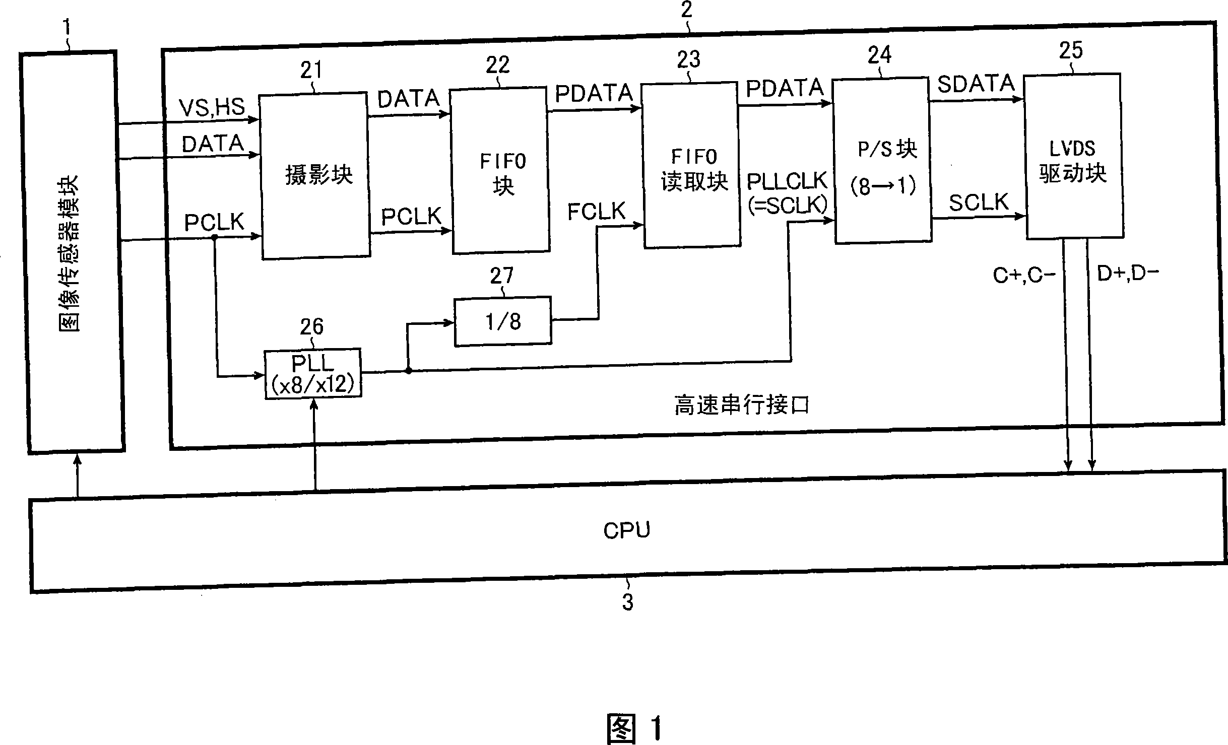
[0032] FIG. 1 is a block diagram showing an embodiment of an image forming apparatus according to the present invention. Some examples of image forming apparatuses to which the present invention is applicable include digital still cameras and digital video cameras (including, for example, PDAs (Personal Digital / Data Assistants) and portable telephone terminals having a camera function), and scanners.

[0033] As shown in FIG. 1, the image forming apparatus of this embodiment includes: an image sensor module 1, a high-speed serial interface device 2 (hereinafter referred to as "serial I / F" 2) and a central processing unit 3 (hereinafter referred to as "CPU"). "3).

[0034] The image sensor module 1 converts an optical signal obtained from a subject into an electrical signal by using a CCD (Charge Coupled Device) image sensor or a CMOS (Complementary Metal Oxide Semiconductor) image sensor, thereby generating an image signal DATA following its output format. It is to be noted t...


PUM


Abstract

A serial I / F has: a FIFO portion to which m- or n-bit (m H04N 1 / 00 G06F 13 / 38 H03L 7 / 06 6 9 2 2007 / 5 / 18 101079939 2007 / 11 / 28 000000000 Rohm Co., Ltd. Japan Murata Tatsuhiko Fujiwara Masayu Yamamoto Tomoki Matsuzaki Takeshi zhujin gui 11021 The Patent Agency of the Chinese Academy of Sciences Inside the Chinese Academy of Sciences, No.52 Sanlihe Road, Fuwai, Beijing 100864 Japan 2006 / 5 / 23 2006-142654

Description

technical field [0001] The present invention relates to a serial interface device having a plurality of input bus widths, and to an image forming apparatus using such a serial interface device. Background technique [0002] In an image forming apparatus such as a digital still camera, a digital video camera, or a scanner, an image signal (pixel signal) obtained by an image sensor module is typically input in parallel to a serial interface device provided near the image sensor module, and then Which undergoes predetermined image processing. Then, only the processing results thus obtained are serially output to a central processing unit (hereinafter referred to as "CPU"). [0003] Furthermore, as the above-mentioned image sensor module, an image sensor module using different output formats having different output bus widths, such as a YUV output format and a RAW output format, has recently been proposed. This is due to the pursuit of highly versatile serial interface devices...

Claims


Application Information

Patent Timeline
Patent Type & Authority Applications(China)
IPC IPC(8): H04N1/00G06F13/38H03L7/06
CPCG06F2205/061G06F5/06H03M9/00
Inventor 村田达彦藤原正勇山本智树松崎刚
Owner ROHM CO LTD
Features
  • Generate Ideas
  • Intellectual Property
  • Life Sciences
  • Materials
  • Tech Scout
  • Unparalleled Data Quality
  • Higher Quality Content
  • 60% Fewer Hallucinations
Learn More