Rotor for motor and manufacturing method therefor

A motor and rotor technology, applied in the field of bonded magnet rotors for motors, can solve problems such as difficulty in easily magnetizing shafts

Inactive Publication Date: 2007-11-28
HITACHI METALS LTD
View PDF5 Cites 25 Cited by
  • Summary
  • Abstract
  • Description
  • Claims
  • Application Information

AI Technical Summary

Problems solved by technology

However, for the reasons described above, it is extremely difficult to align the axes of easy magnetization without deviation in an anisotropic magnet rotor regardless of radial orientation or multi-pole orientation.

Method used


Image

  • Rotor for motor and manufacturing method therefor
  • Rotor for motor and manufacturing method therefor
  • Rotor for motor and manufacturing method therefor

Examples


Embodiment 1

[0096] Embodiment 1, comparative example 1

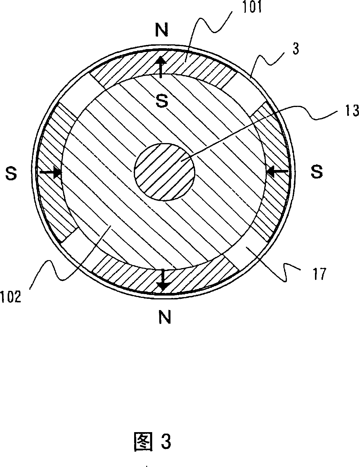
[0097] First, the advantages of the manufacturing method of the present invention, that is, the effective use of the bonding strength between the bonded magnet portion and the soft magnetic yoke portion, and the effect of abolishing the guard ring will be studied. In the conventional method of bonding sector magnets (comparative example 1), as shown in FIG. 3 , a guard ring is necessary. In view of this point, when using the rotor produced by the manufacturing method of the present invention (Fig. 1(a)), since the rare earth bonded magnet portion and the soft magnetic yoke portion composed of soft magnetic powder can be firmly integrated, A guard ring is not required, and since the gap between the stator and the rotor can be reduced, the magnetic flux of the magnet can be used more effectively than Comparative Example 1. It is also possible to avoid an output drop caused by eddy current loss in the guard ring in the high-frequency ...

Embodiment 2

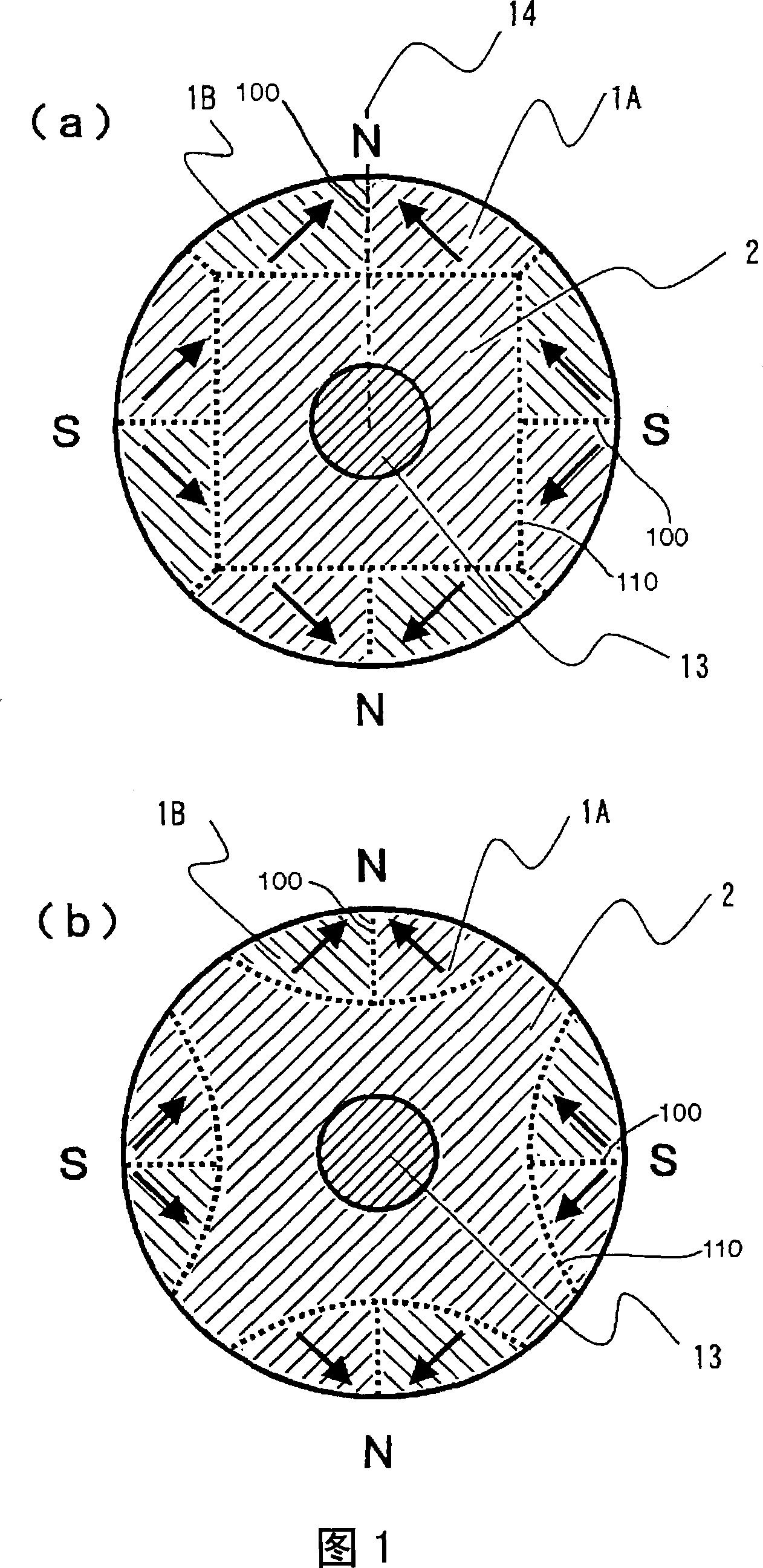
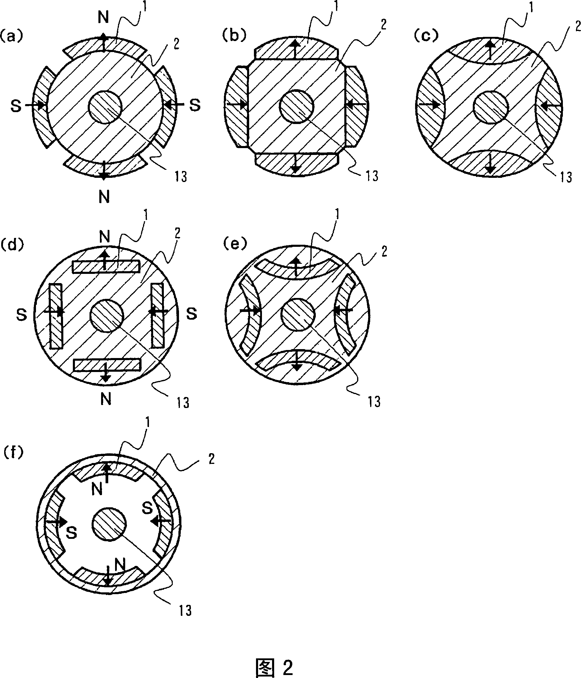
[0104] Fig. 1 is a schematic sectional view of a permanent magnet rotor according to another embodiment of the present invention. In FIG. 1, two magnets 1A, 1B, a yoke 2 made of soft magnetic material, and a shaft 13 constitute one magnetic pole. A plurality of such complicated shapes and orientations of permanent magnets can be provided by the manufacturing method of the present invention. As shown in Fig. 1, when the magnetization direction of the magnet is joined in a line-symmetric manner with respect to the joining surface 100 (the dotted line connecting N and S in the figure), the generated magnetic field is efficiently concentrated on the magnetic pole indicated by N(S) in the figure At the central position, higher magnetic properties can be obtained compared to the structure in which one magnetic pole is constituted by a single magnet as shown in FIG. 2 . The concentration of the generated magnetic field is related to the magnetic inclination. The magnet material, si...

Embodiment 3

[0107] Fig. 10 is a schematic sectional view of a permanent magnet rotor according to another embodiment of the present invention. In the conventional ring magnet manufacturing method, as shown in Fig. 10(a), orientation and multi-pole orientation of magnets having a large thickness in the direction of magnetization are difficult, but in the manufacturing method of the present invention, regardless of the poles of the magnet Regardless of the number and size, stable orientation and magnetization can be easily performed. In addition, as shown in FIG. 10( b ) and FIG. 10( c ), even if one pole is constituted by three magnets 1A to 1C, the generated magnetic field can be efficiently concentrated at the center of the magnetic pole.


PUM

PropertyMeasurementUnit
particle sizeaaaaaaaaaa
shear strengthaaaaaaaaaa
particle sizeaaaaaaaaaa

Abstract

A surface magnet-type and inner magnet-type rotors having high bonding strength between a magnet section and a soft magnetic yoke section, and exhibiting high structural reliability and good motor characteristics even in a high-speed application. Methods of manufacturing the rotors are also provided. The surface magnet-type rotor is composed of an anisotropic bond magnet section and a soft magnetic section. To manufacture the surface magnet-type rotor, the anisotropic bond magnet section is preliminarily molded in a magnetic field, and then molded finally in a nonmagnetic field to be integrated with the soft magnetic section and heat cured. Magnetic units each having magnetic poles formed by bonding a pair of permanent magnets such that the directions of magnetization are symmetric about the bonding surface are connected to form an anisotropic magnet body, in which the magnetic units are arranged such that magnetic poles of different polarities appear alternately on a magnetism action surface. Good motor characteristics are attained by setting the direction of magnetization of the permanent magnets at an angle of 5-35 DEG relative to the radial direction passing the bonding surface.

Description

technical field [0001] The present invention relates to a bond magnet rotor for an electric motor integrated with a soft magnetic yoke for the purpose of increasing the efficiency of electric motors and generators using permanent magnets. Background technique [0002] Currently, various structures have been devised for magnet rotors for electric motors, and they can be classified into two types. The first form is a so-called Surface Permanent Magnet (SPM) rotor in which permanent magnets are arranged on the surface of the magnets, as shown in FIGS. 2( a ) to ( c ) and ( f ). On the other hand, as shown in FIG. 2(b)(e), the second method is a magnet-embedded (Interior Permanent Magnet, hereinafter referred to as IPM) rotor in which permanent magnets are arranged inside the rotor. The former SPM rotor has permanent magnets arranged on the surface of the rotor and faces the stator with an air gap in between. Compared with the latter IPM rotor, it has the advantage of being eas...

Claims


Application Information

Patent Timeline
Patent Type & Authority Applications(China)
IPC IPC(8): H02K1/27H02K1/02H02K15/03H01F41/02
CPCH02K1/278H01F41/0266H01F41/028H02K1/2733H02K15/03
Inventor 增泽正宏三田正裕菊地庆子
Owner HITACHI METALS LTD
Why Eureka
Try Eureka