Drilling fluid treatment system

A technology for processing systems and drilling fluids, which is used in earth-moving drilling, flushing wells, wellbore/well components, etc. The effect of workload

Active Publication Date: 2007-12-05
CHINA NAT OFFSHORE OIL CORP +1
View PDF1 Cites 31 Cited by
  • Summary
  • Abstract
  • Description
  • Claims
  • Application Information

AI Technical Summary

Problems solved by technology

However, the processing system with conventional configuration has the following problems: 1. The vibrating screen is often blocked, which seriously affects the processing capacity and service life of the vibrating screen; 2. When preparing drilling fluid, it is generally used by the staff Adding ashes or chemical preparations directly into the mud pool or mixing funnel by hand cannot be accurately measured; not only that, most liquid additives will emit dazzling, pungent and other harmful odors to human health, and some have strong acid or Alkaline, which makes this work a greater safety hazard

Method used


Image

  • Drilling fluid treatment system

Examples


Embodiment Construction

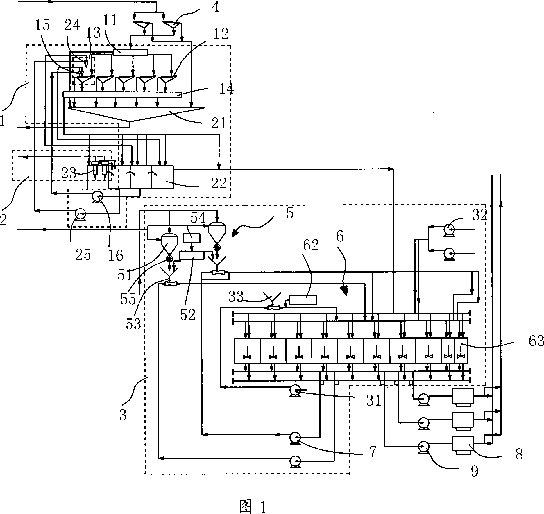
[0012] As shown in Figure 1, the present invention includes: a silt removal part 1, a degassing part 2 and a recombination part 3, and the drilling fluid returned from the wellhead passes through the silt removal part 1 and the degassing part 2 respectively to remove drilling cuttings such as mud and sand After mixing with natural gas, ash and liquid chemicals are compounded in the compounding part 3; a mud scraper 4 for removing sticky mud cakes in the drilling fluid is also provided upstream of the mud and sand removal part 1, as described below in detail.

[0013] In Fig. 1, the desilting part 1 includes: a flow divider 11, a vibrating screen 12, a mud cleaner 13, a desilter 15, a desander 24, a mud return tank 14, a desilter pump 16, a sand discharge tank 21, a settling Sand pool 22, sand removal pump 25. The mud scraper 4 is arranged at the upstream of the desilting part 1, that is, at the upstream end of the flow divider 11, like this, the mud returned from the wellhead ...


PUM


Abstract

The invention discloses a processing system of drilling liquor which contains the sand removing part (1), the air removing part (2) an the return-service part (3). The drilling liquor returning from the portal eliminates the debris and natural gas by passing the sand removing part (1) and the air removing part (2) sequentially. Build into ash and liquid chemical agent in the return-service part (3). A sludge scraper (4) used for eliminating clay cake in the drilling liquor is set at the upstream of the sand removing part (1) (the upstream end of the splitter). The slurry returning from the portal passes the sludge scraper firstly to eliminate the clay cake. Therefore, it reduces the workload of the vibrating shaker at the downstream greatly and avoids the clay cake adhering shaker or bulking shaker, which improves the handing capacity and prolongs the service life of the vibrating shaker.

Description

technical field [0001] The invention relates to a drilling fluid treatment system for petroleum and geological drilling. Background technique [0002] In oil drilling operations, the performance of drilling fluid plays a decisive role. Unreasonable control of the solid phase of the drilling fluid may lead to well collapse, kick, blowout or fracturing the formation and pollute the formation, leading to serious consequences such as failure to discover or destroy potential oil and gas resources. [0003] The drilling fluid treatment system is composed of the drilling fluid solid phase control system and the drilling fluid preparation system. Add ash and chemical additives to the drilling fluid to make the drilling fluid achieve the desired properties such as density and viscosity. Chinese patent 91102428.X discloses a drilling fluid treatment system, which includes a vibrating screen, degasser, desander, desilter, cleaner, drilling fluid connection equipment, drilling fluid s...

Claims


Application Information

Patent Timeline
Patent Type & Authority Applications(China)
IPC IPC(8): E21B21/06
Inventor 刘宝元褚寅秋姜渭渔陈力生蒋德超宋春旺
Owner CHINA NAT OFFSHORE OIL CORP
Why Eureka
Try Eureka