Omnidirectional radiative microstrip aerial
A technology of microstrip antenna and omnidirectional radiation, which is applied in the field of wireless communication, can solve the problems of unrealized omnidirectional radiation, and achieve the effect of low cross polarization level and low profile
- Summary
- Abstract
- Description
- Claims
- Application Information
AI Technical Summary
Problems solved by technology
Method used
Image
Examples
Embodiment 1
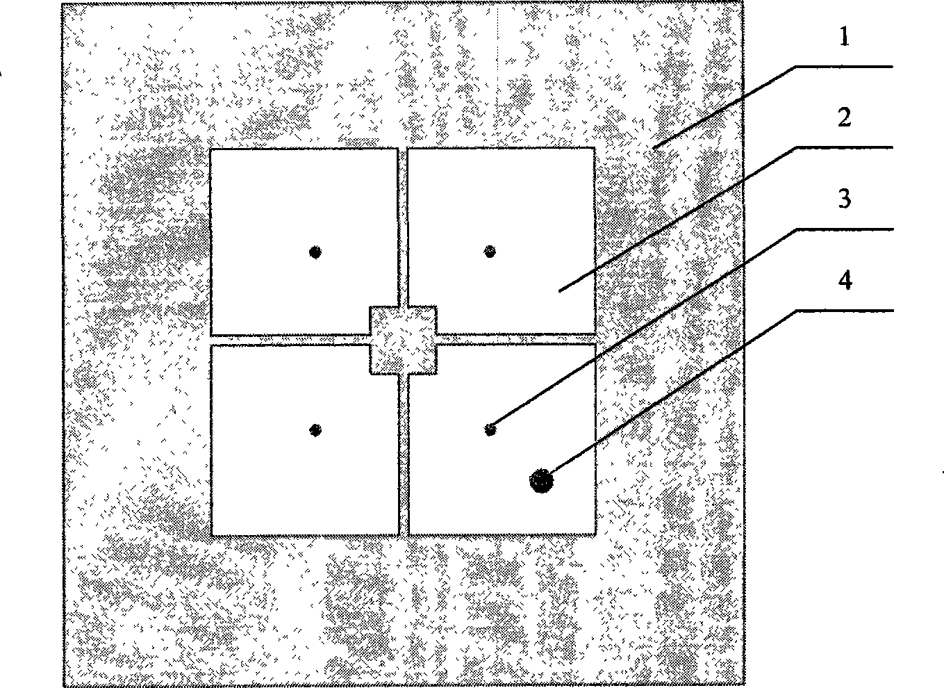
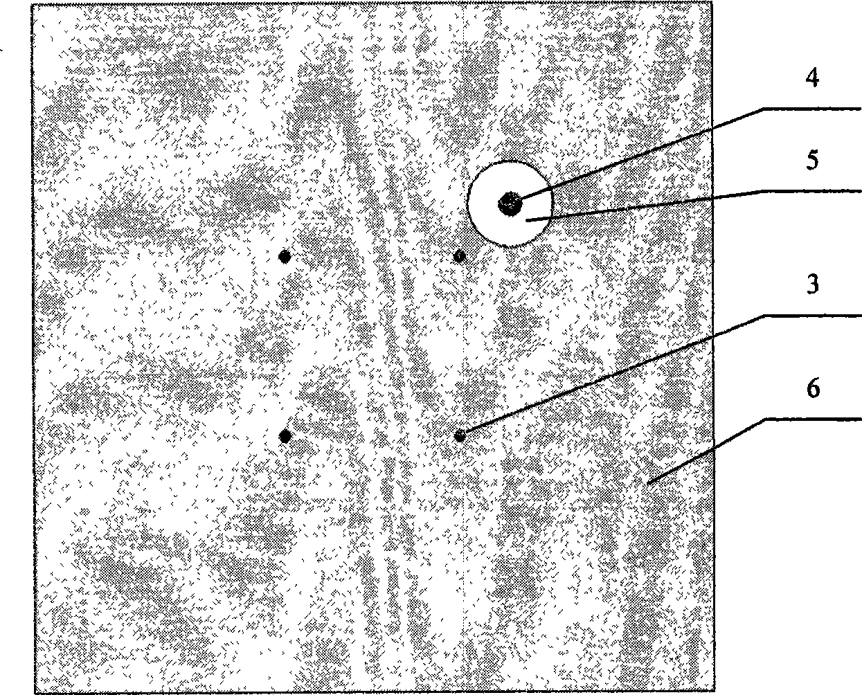
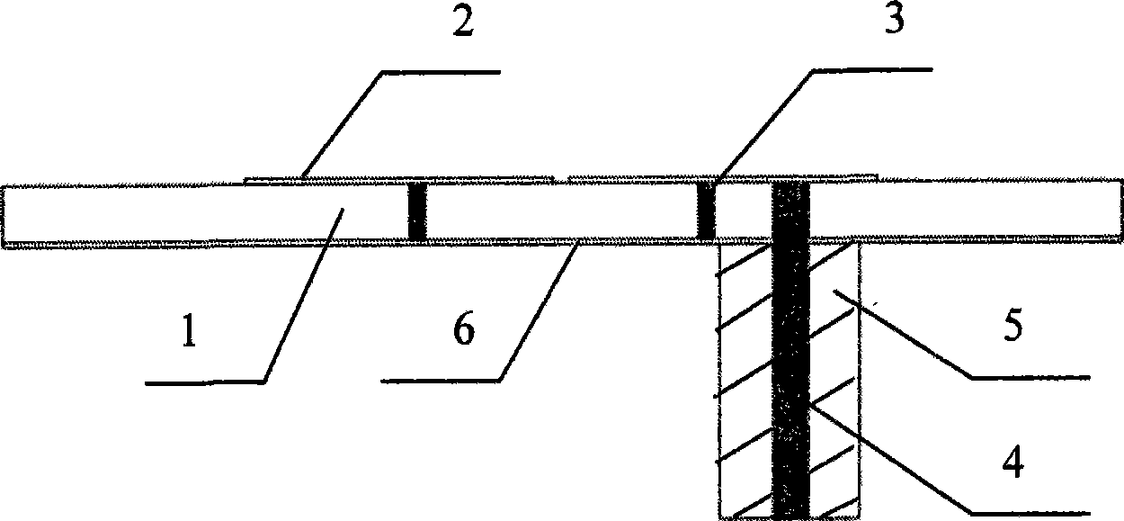
[0023] Example 1: first refer to Figure 1~3 The structural diagram of the microstrip antenna of the present invention is described.
[0024] The bottom surface of the dielectric substrate 1 is a metal floor 6 , and the upper surface of the substrate 1 is a radiation metal patch 2 . The metal floor 6, the dielectric substrate 1 and the radiating metal patch 2 are placed in parallel sequentially from bottom to top. The metal via 3 passes through the dielectric substrate 1 vertically, connects the metal floor 6 and the radiating metal patch 2, and a radio frequency coaxial connector SMA connector connects the radiating metal patch 2 and the metal grounding plate 6, and serves as a feeder for the antenna radio signal Incoming interface. The inner core 4 of the SMA coaxial joint passes through the small hole of the same size drilled on the metal ground plate 6 and the dielectric substrate 1 is connected to the radiation metal patch 2, while the metal outer wall of the outer core...
Embodiment 2
[0028] Embodiment 2: refer to Figure 7 , still use the FR4 dielectric substrate with a relative dielectric constant of 4.4 and a size of 40mm×40mm×2mm. The outer contour side length of the radiation metal patch is 22.6mm, the inner contour side length is 4mm, the radius of the metal via hole is 0.3mm, and the adjacent via hole The distance between them is 10.8mm, and the gap width is 0.2mm. In this case, each radiating metal patch of the antenna contains two or more metal vias. This is equivalent to increasing the diameter of the metal via, the equivalent parallel inductance becomes smaller, and the zero-order resonance frequency will become higher. The zero-order resonance of this antenna occurs at 4.4GHz, and omnidirectional radiation can also be achieved at this frequency.
Embodiment 3
[0029] Embodiment 3: refer to Figure 8 , the radiating metal patch of the antenna can be not only rectangular, but also circular, or other shapes, while satisfying the symmetry of the antenna with respect to the normal of the antenna plane, because their equivalent circuits are the same, only the equivalent value Different, it will only affect the working frequency of the zero-order resonance, and both have the performance of omnidirectional radiation. Only the shape of the radiating metal sheet of this antenna is different from that of the foregoing embodiments, and the rest are similar, so details will not be repeated here.
PUM
 Abstract
Description
Claims
Application Information
 - R&D
- Intellectual Property
- Life Sciences
- Materials
- Tech Scout
- Unparalleled Data Quality
- Higher Quality Content
- 60% Fewer Hallucinations
Browse by: Latest US Patents, China's latest patents, Technical Efficacy Thesaurus, Application Domain, Technology Topic, Popular Technical Reports.
© 2025 PatSnap. All rights reserved.Legal|Privacy policy|Modern Slavery Act Transparency Statement|Sitemap|About US| Contact US: help@patsnap.com


