Generalized force application magnet and conductor rail magnetic suspension vehicle or train using the same

A magnetic levitation, magnet technology, applied in vehicle components, excitation or armature current control, electric vehicles, etc., can solve problems such as increasing the weight of the locomotive, lack of transportation versatility, network and compatibility, and inability to use

Inactive Publication Date: 2007-12-05
田景华
View PDF1 Cites 16 Cited by
  • Summary
  • Abstract
  • Description
  • Claims
  • Application Information

AI Technical Summary

Problems solved by technology

[0012] Above-mentioned all kinds of maglev trains, no matter use electromagnetic, permanent magnet or superconducting magnet, no matter magnet and coil etc. are placed on track bottom, side or top; Their common shortcoming is that all must expend huge sums of money to build special-purpose line , completely unable to use existing railway tracks and other line facilities, and does not have the "universality, network and compatibility" of transportation
"In order to pull heavy-duty trains, it is often necessary to use weighted iron to increase the weight of the locomotive, and even to sprinkle sand in some areas; these all increase the wear between the rail wheels

Method used


Image

  • Generalized force application magnet and conductor rail magnetic suspension vehicle or train using the same
  • Generalized force application magnet and conductor rail magnetic suspension vehicle or train using the same
  • Generalized force application magnet and conductor rail magnetic suspension vehicle or train using the same

Examples


Embodiment Construction

[0160]Below in conjunction with the accompanying drawings and specific embodiments, "object 1" of the present invention is described in further detail:

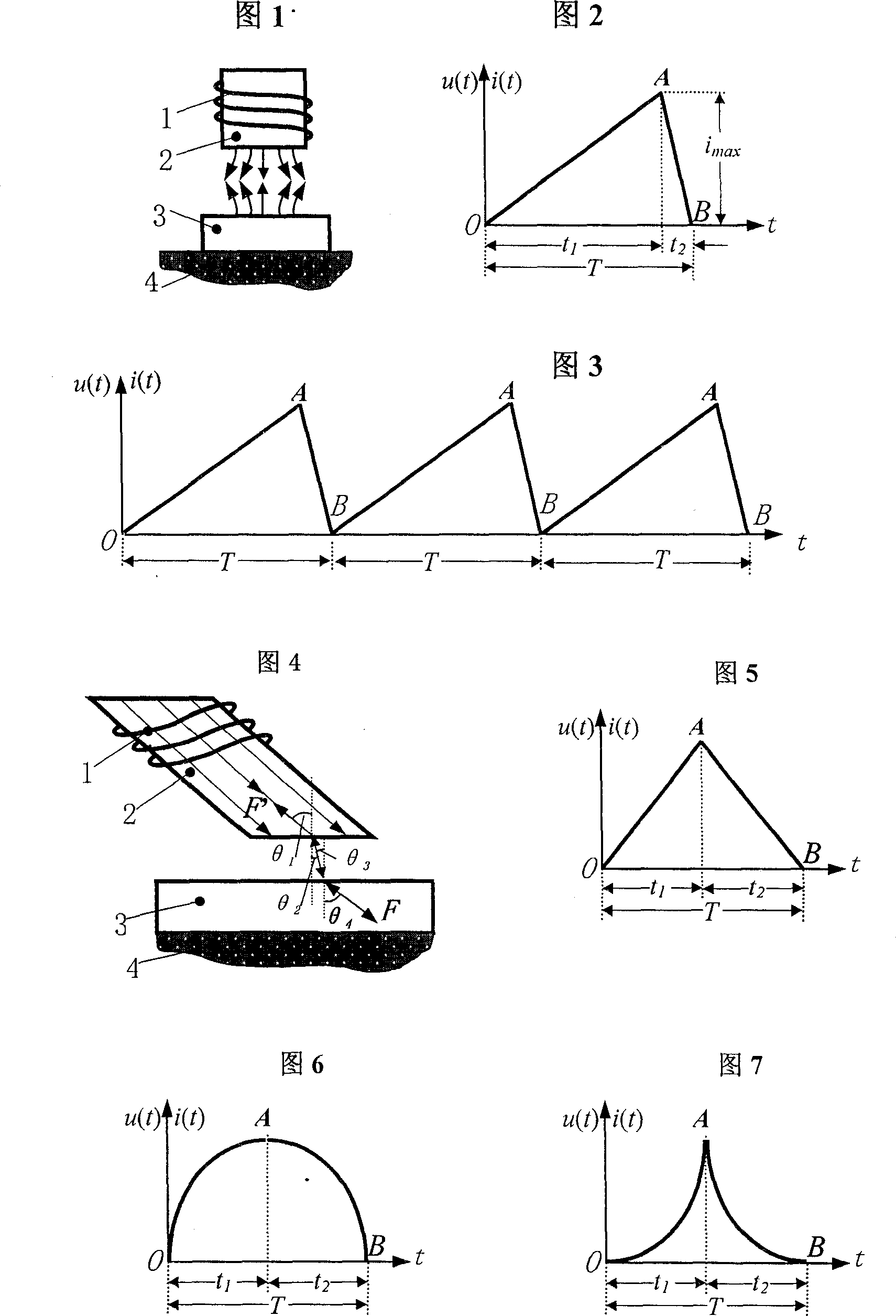
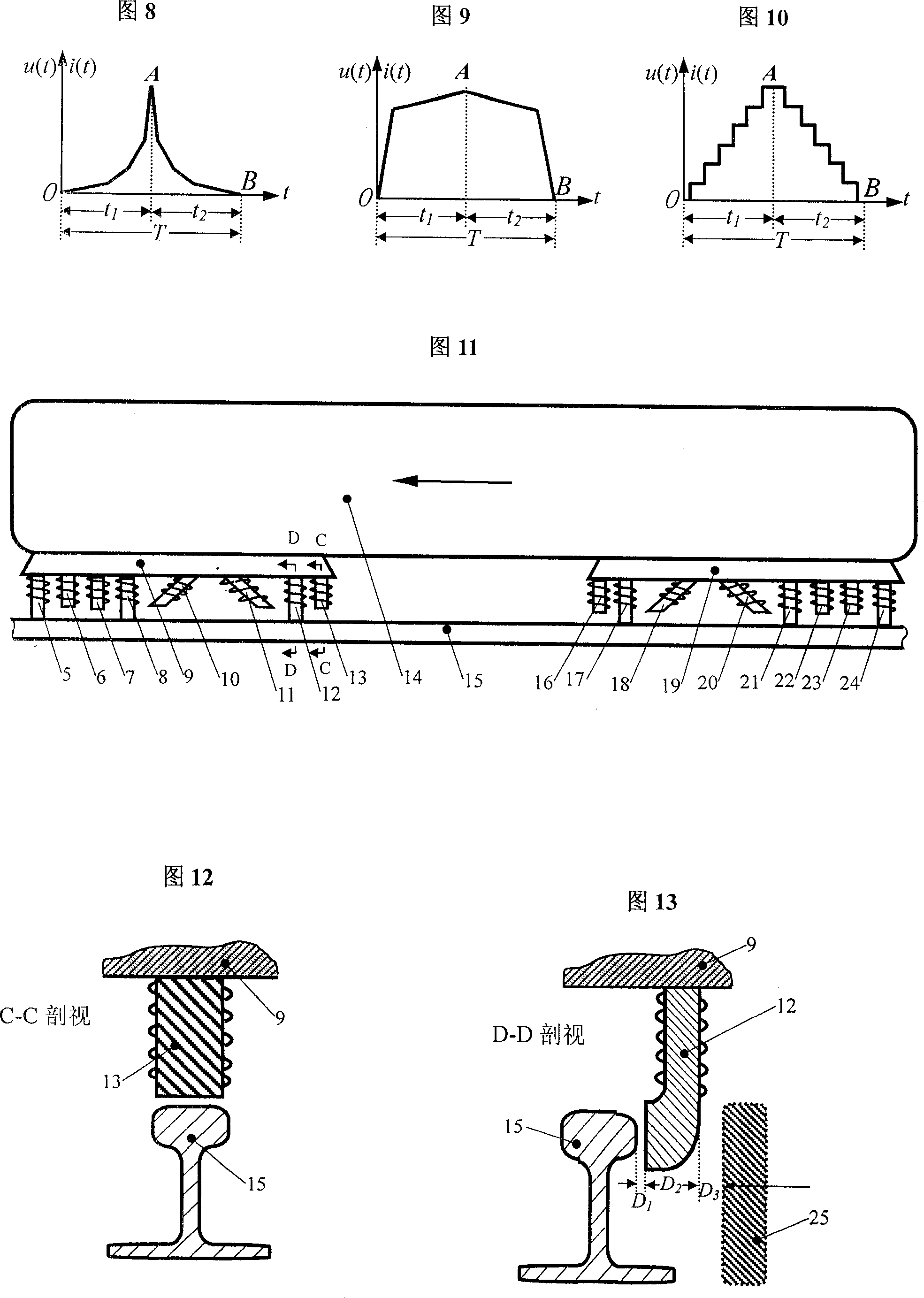
[0161] As mentioned above: the function u(t) of the voltage at both ends of the coils of the three magnets of the present invention changes with time t or the function i(t) of the current passing through the coil with time t is a pulse and has a rising and a rising value. down. The waveform of u(t) or i(t) of the vibrating magnet coil 1 may be a linear triangular wave in FIG. 5 . can be the curve in Figure 6: at time t 1 , du / dt or di / dt is initially large and then gradually decreases; and at time t 2 , the absolute value |du / dt| or |di / dt| is initially small and then gradually increases. Or the curve in Figure 7: at time t 1 , du / dt or di / dt is initially small and then gradually increases; at time t 2 , |du / dt| or |di / dt| is initially larger and then gradually decreases. By extension: at t 1 and t 2 Inside, the curve...


PUM


Abstract

The invention relates to a generalized force magnet, which forms the magnetic flux change of using the rise and drop change of the voltage or the current pulse in the coil, thus has the induced electromotive force, the induced current and the reverse induction field in the conductor. Through regulating the time ratio, pulse waveform and so on of impulse in the electric current rise and drop to realize the repelling force, the attraction or the vibration power which is exerted on all conductors, and enables this magnet to maintain separates or mutual attraction relatively static or back and forth vibrates with each kind of conductor. One kind magnetic suspension vehicles or the train which used the above magnet, provides the separation aerosol magnet, the guidance magnet, the actuation magnet, the brake / back-draft magnet in the bogie or the frame of the locomotive and lower part vehicles (and essential degaussing magnet); the kind of vehicles no need to rebuild the existing railroad to realize high speed or / heavy load travel on the conductor track specially on the existing railroad.

Description

technical field [0001] The present invention relates to a type of force-applying magnet and the technical field of using such magnet to suspend, guide, drive, brake or reverse vehicles or / and trains on conductor tracks. Background technique [0002] Existing magnets include: permanent magnets, electromagnets and superconducting magnets; in particular, superconducting magnets can pass a strong current to obtain a strong magnetic field. The same-named magnetic poles of various magnets can repel each other, and the different-named magnetic poles can attract each other; various types of magnets can also attract a few types of ferromagnetic substances such as iron, cobalt, and nickel. However, all kinds of magnets, including superconducting magnets, cannot exert repulsive, attractive or vibrating forces on "normal" conductors other than ferromagnetic substances. [0003] In order to enhance the magnetic flux of the existing electromagnet, in addition to the iron core, the number...

Claims


Application Information

Patent Timeline
Patent Type & Authority Applications(China)
IPC IPC(8): H02P7/06H02K41/02B60L13/03
Inventor 田景华
Owner 田景华
Why Eureka
Try Eureka