
Deuterium lamp lighting detection recognizing device

A lighting detection and recognition device technology, which is applied in the direction of lighting devices, lamp circuit layout, discharge tube testing, etc., can solve problems such as false signals, photoelectric sensor installation is easily restricted by position, and sensor life is limited, so as to achieve long service life , The effect of low device price and low production cost

Inactive Publication Date: 2007-12-05
安徽蓝盾光电子股份有限公司
View PDF0 Cites 1 Cited by
  • Summary
  • Abstract
  • Description
  • Claims
  • Application Information

AI Technical Summary

Problems solved by technology

The disadvantages of this method are: 1. The use of photoelectric sensors to receive light signals is prone to false signals due to interference from external light, especially in the debugging process; 2. The installation of photoelectric sensors is easily limited by the location; 3. The sensor has a limited lifespan when detecting some strong UV light sources

Method used


Image

  • Deuterium lamp lighting detection recognizing device

Examples


Embodiment Construction

[0014] Below in conjunction with accompanying drawing, the present invention is described in further detail:

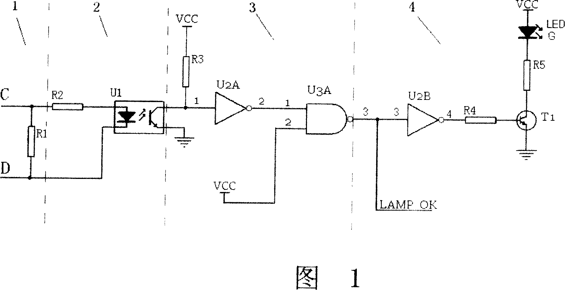
[0015] The resistance R of the signal sampling circuit 1 1 It is connected in parallel on C and D at both ends of the deuterium lamp, and the trigger circuit 2 uses an optical coupler U 1 , the high-low level conversion circuit 3 consists of an inverter U 2A And NAND gate U 3A Composed of, the display circuit 4 consists of an inverter U 2B , by R 5 , T 1 , R 4 Composed of driving circuit and light emitting diode G composition. When the light is off, the resistor R 1 Almost no current flows on the R 1 The voltage at both ends is almost zero, at this time the photocoupler U 1 Not working. When the lamp is on, the resistor R 1 There is current flowing, and the R 1 A certain voltage difference is formed at both ends, as long as R is adjusted 1 resistance value, R 1 Generate enough voltage on the optocoupler U 1 work so that the inverter U 2A The level of t...


PUM


Abstract

The present invention discloses a deuterium lamp lighting detection and identification device, and it includes a signal sampling circuit 1,high-low conversion circuit 2, trigger circuit 3, Display Circuit 4, when deuterium lamp was lit, voltage signal obtained by sampling circuit makes electric level output by high-low level conversion circuit high-low transform through the trigger circuit, a computer control system would receive the signal, and could automatically judge whether deuterium lamps has been lit. The display circuit would send out the display signal which could be manually judged. The sampled signals of this invention would not be affected by the interference of outside light, and the detection signal is stable. Error trigger would not happen. This invention uses the resistance as the signal sampling devices, so the installation position of sampling devices would be unrestricted and would be free from the impact of UV light, so it would have long service life.

Description

technical field [0001] The invention relates to a device for detecting and identifying whether a deuterium lamp is lit. Background technique [0002] In some optical instruments using ultraviolet light sources, such as the continuous monitoring system for flue gas emission produced by our company, deuterium lamps are often used as ultraviolet light sources. The deuterium lamp is generally required to be enclosed inside the instrument, and the state of the light source is often unclear. In order to provide the control circuit, that is, the single-chip microcomputer, with an automatic discrimination signal whether the deuterium lamp is on or not, and as an indication signal for manual discrimination, it is necessary to detect whether the deuterium lamp is on. and instructions. People have taken various measures for this reason, and a common one is exactly to utilize the photoelectric sensor to receive the light signal, convert the light signal into an electrical signal and di...

Claims


Application Information

Patent Timeline
Patent Type & Authority Applications(China)
IPC IPC(8): H05B41/14G01R31/24H05B37/03
Inventor 鲁爱昕徐合林
Owner 安徽蓝盾光电子股份有限公司
Learn More