
Valve capable of draining water

A technology for drainage and water interception, which is applied in the direction of water supply devices, water supply main pipelines, water supply pipeline systems, etc., to achieve the effects of increasing the drainage path, shortening the drainage path, and increasing the drainage speed

Inactive Publication Date: 2007-12-12
TAKEMURA
View PDF0 Cites 5 Cited by
  • Summary
  • Abstract
  • Description
  • Claims
  • Application Information

AI Technical Summary

Problems solved by technology

In addition, since the seat of the drain stopper is in flat contact with the seat surface on the side of the water hole, there are serious problems such as water leakage in the middle

Method used


Image

  • Valve capable of draining water
  • Valve capable of draining water
  • Valve capable of draining water

Examples


no. 1 example

[0027] First, the first embodiment will be described with reference to Figs. 1 to 7.

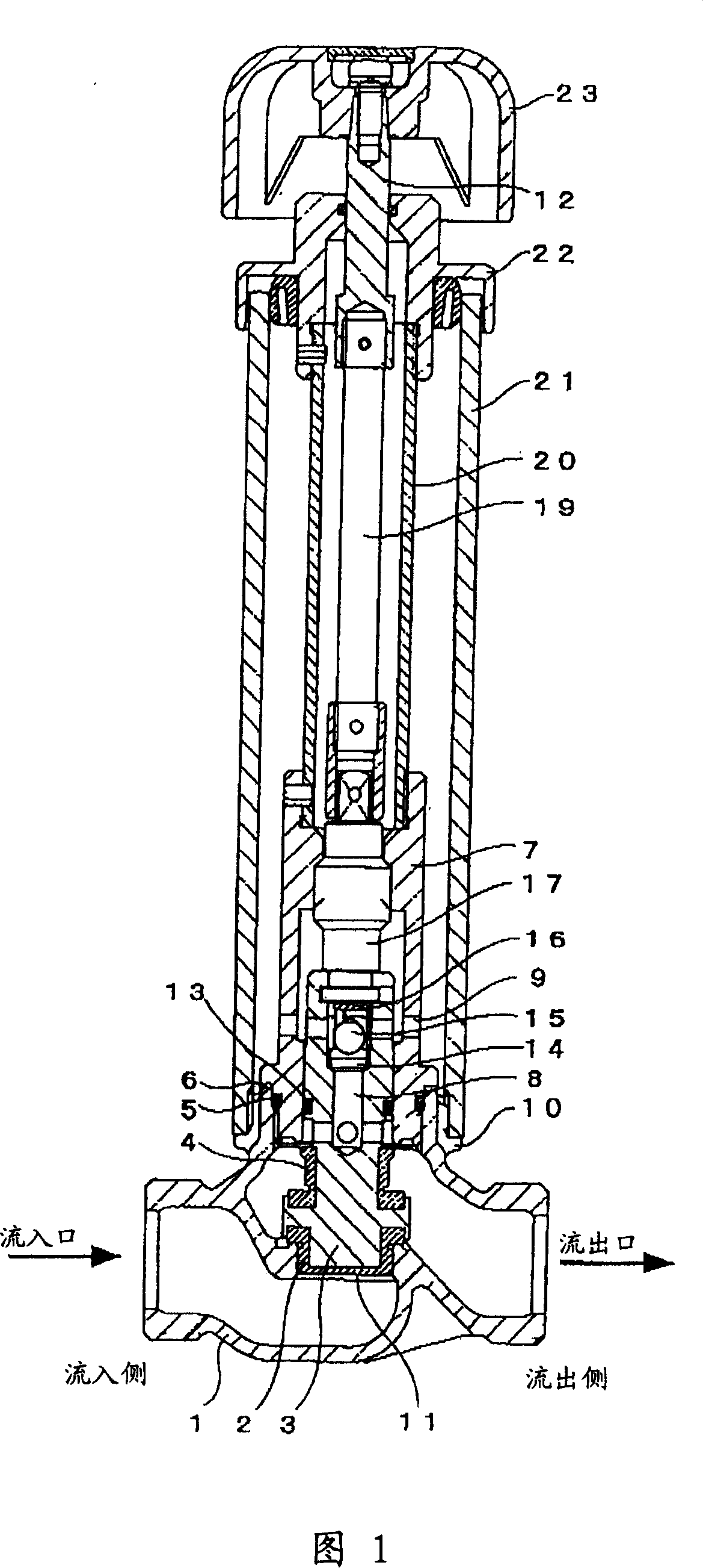
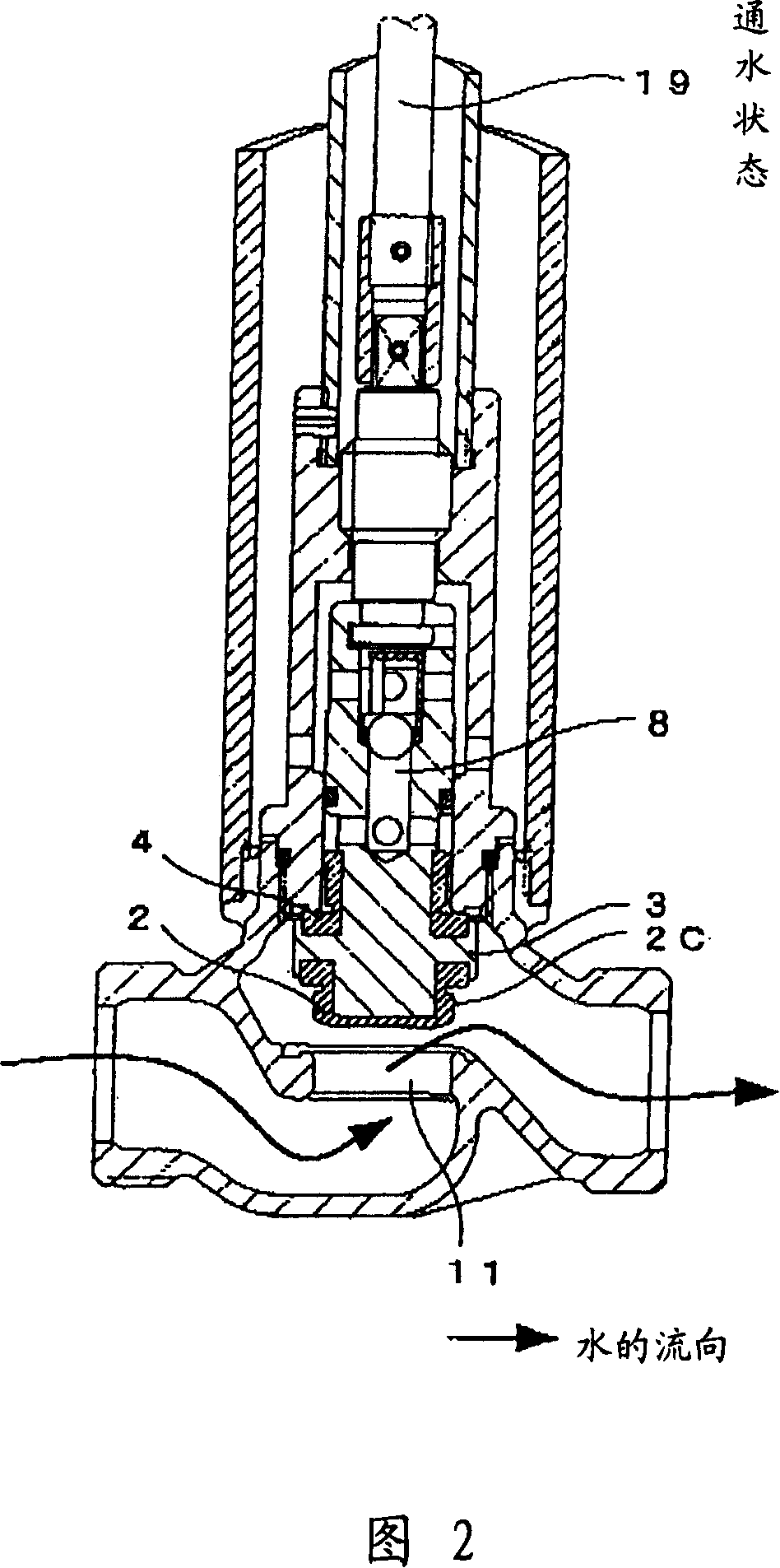
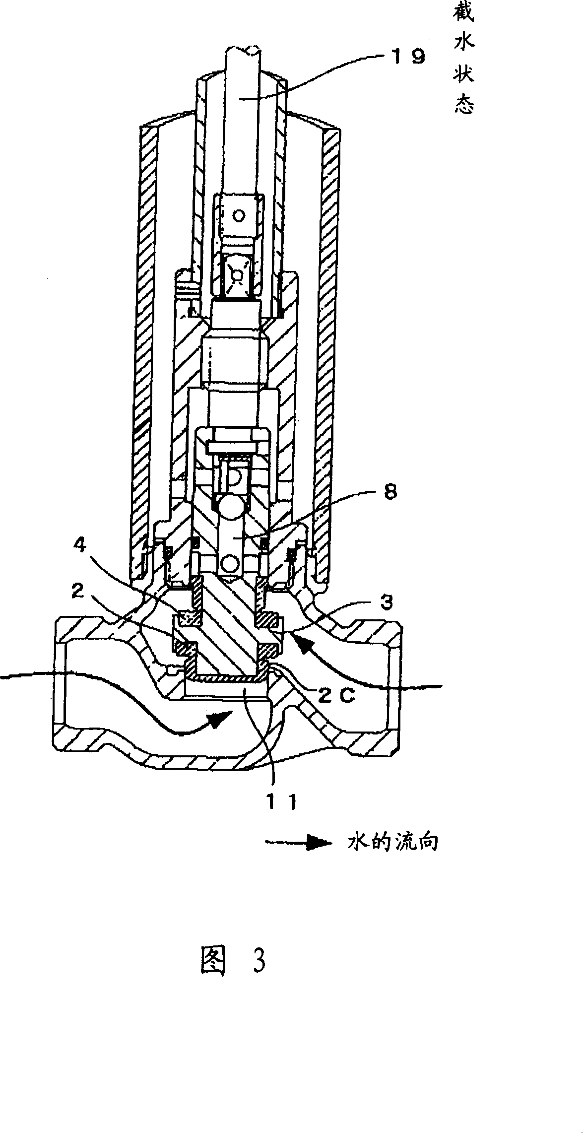
[0028] Fig. 1 is a front cross-sectional view showing a drain hydrant of the first embodiment of the present invention, and Fig. 2 is a partial front cross-sectional view of the drain hydrant of Figure 1, and Fig. 3 is a partial front cross section of the drain roller cut in Fig. 1. Fig. 4 is a partial front cross section, and Fig. 5 (a), Fig. 5 (b), and Fig. 5 (c) are a cut-off sem in accordance with a first embodiment of the present invention for the first embodiment of the present invention. Positive cross-sectional view of the pieces, Figure 6 (a), Figure 6 (b), Fig. 6 (c) is a front cross-sectional view of the ball guide for the drain hydrants of the first embodiment of the present invention. As shown in the figure and bottom, Fig. 7 (a), Fig. 7 (b) is a front cross-sectional view of a lip gasket for the drain hydrants and the above view of the first embodiment of the present invention. The...

no. 2 example

[0037] Next, the second embodiment will be described with reference to FIGS. 8 and 9.

[0038] Figure 8 is a front cross-sectional view of the drain plug of the second embodiment of the present invention, Figure 9 (a), Figure 9 (b), Figure 9 (c) is the second embodiment of the present invention for the interception of the drain plug The front cross-sectional view, top view and bottom view of the piece. This embodiment has the feature of installing a safety valve that releases the abnormal pressure generated on the outflow side on the interceptor.

[0039] The drain plug of this embodiment has a plug main body 1, an operation lever 19 of the operation plug main body 1, and a handle 23 that drives the operation lever 19 up and down. The plug main body 1 has: an inflow-side inflow port, an outflow-side outflow port formed on the side of the plug main body 1, a water passage having a water through hole 11 provided between the inflow port and the outflow port, and is detachably fitted ...


PUM


Abstract

The present invention relates to a drainage plug, which intermittently fits the fitting portion of the plug body and the outer cylinder to form a gap. It does not require multiple drainage outlets in the past, and does not require a sand-cutting cover. It has good drainage performance and water interception. The stopper is detachably fitted on the lower mandrel and has a drainage path, and integrates a water-cutting gasket covering the front end and a drainage gasket that is spaced and opposite to the water-cutting gasket, and the water-cutting gasket and drainage gasket are The gasket is easy to replace and there is no intermediate water leakage. The water-cutting gasket consists of a protruding part covering the central part of the front end and a peripheral part connected at right angles to the protruding part. The part of the peripheral part that is connected to the protruding part has a U-shaped cross-section. The outer surface of the protruding portion has a partially R-shaped groove, and the drain gasket has a groove with a U-shaped cross section at the peripheral portion that is in contact with the protruding portion.

Description

Technical field [0001] The present invention relates to a drain hydrant for a water channel system. Background technique [0002] In the waterway system in the cold zone, the drainage hydration such as antifreeze is connected to the water channel. An example of a conventional drain hydrant will be described with reference to Fig. 11. The figure is a front cross-sectional view of the drainage plug (hereinafter referred to as an unfroken water) described in Patent Document 1. The handle 110 of the upper and lower drive operating lever 112 is mounted on the upper portion of the drain. The handle 110 is connected to the operating lever 112 in the inner portion of the drain hydrant 107, and the operating rod 112 is interposed with a down-axis of the lower end shaft in which it is connected to the lower end. The drain suppression has the following characteristics, to prevent the intermediate drain at the time of the valve switching, and the drainage hole is performed after the entire p...

Claims


Application Information

Patent Timeline
IPC IPC(8): F17D3/10
CPCE03B7/10E03B9/027F16K15/04F16K41/006
Inventor 牧岛由和
Owner TAKEMURA
Learn More