A vacuum balance method of vacuum pressure dipping technology and its device

A technology of vacuum pressure impregnation and balance method, which is applied to the device for coating liquid on the surface, insulating conductor/cable, coil manufacturing, etc., can solve the problems of poor impregnation effect and weak insulation strength, and achieves low cost and insulation. Uniform strength and easy operation

Inactive Publication Date: 2007-12-12
上海同立电工材料有限公司
View PDF0 Cites 12 Cited by
  • Summary
  • Abstract
  • Description
  • Claims
  • Application Information

AI Technical Summary

Problems solved by technology

[0008] As shown in Figure 2, the vacuum painting process schematic diagram of the dipping tank, the straight line part of the motor winding that requires a higher breakdown strength to the ground is sucked in by the pressure between 5000Pa and 40000Pa. The difference between 30-130Pa is

Method used


Image

  • A vacuum balance method of vacuum pressure dipping technology and its device
  • A vacuum balance method of vacuum pressure dipping technology and its device
  • A vacuum balance method of vacuum pressure dipping technology and its device

Examples


Embodiment 1

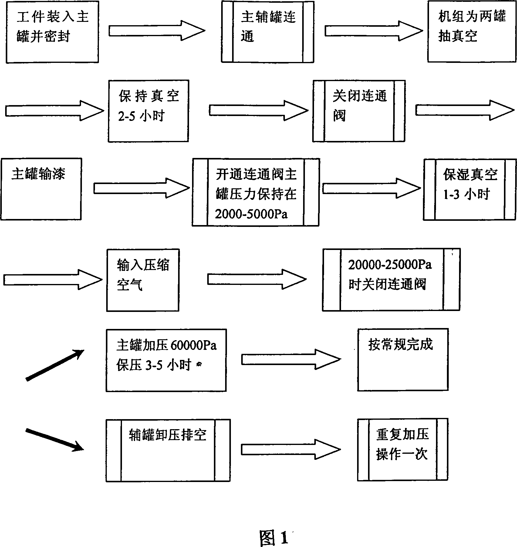
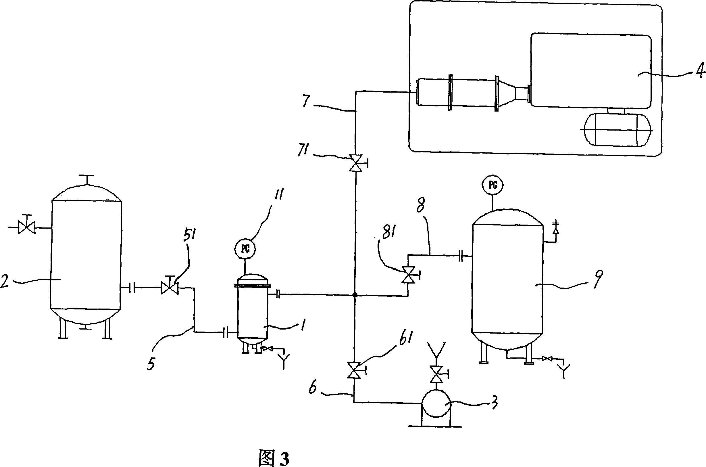
[0041] In Fig. 3, the vacuum pressure impregnation device includes: a paint dipping tank 1, a paint storage tank 2, a vacuum unit 3 and an air compressor unit 4, the bottom of the paint dipping tank 1 communicates with the bottom of the paint storage tank 2 through a paint delivery pipe 5, and The paint pipe 5 is provided with a two-way paint delivery valve 51, the paint delivery pipe 5 can transport the paint in the paint storage tank 2 to the paint soaking tank 1, and can also transport the paint in the paint soaking tank 1 back to the paint storage tank 2, two-way The paint conveying valve 51 is used to control the opening and closing of the paint conveying pipe 5. The upper part of the paint dipping tank 1 communicates with the vacuum unit 3 and the air compressor unit 4 through the pipelines 6 and 7 respectively, and the valves 61 and 71 are set on the pipelines 6 and 7 respectively. The upper part of the varnish tank 1 communicates with an air tank 9 through a communicati...

Embodiment 2

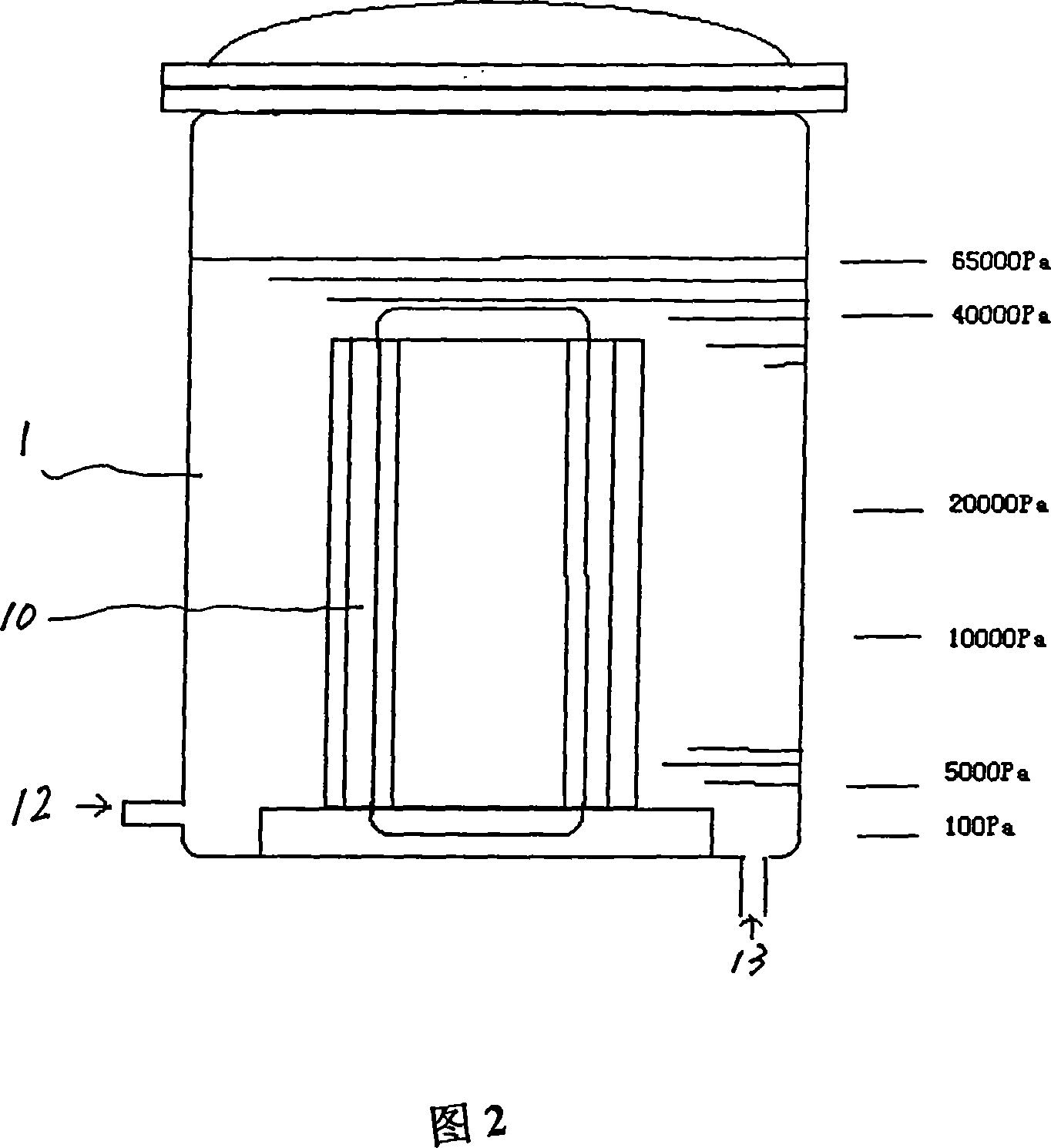
[0053] In the present embodiment, as shown in Figure 4, the balance mechanism is connected with the varnish tank 1' after four gas storage tanks 91, 92, 93, 94 are connected in series.

[0054] In this embodiment, the volume of the gas storage tank is 1-1.5 times that of the varnish tank 1', so as to facilitate the control of the pressure in the varnish tank 1' and keep it at the appropriate vacuum required by the dipping process. within range.

[0055] In this device, the paint dipping tank 1 ' and the paint storage tank 2 ' can also be provided with metering tanks (not shown in the figure); the bottom of the paint dipping tank 1 ' can be connected with a finished product storage tank (not shown in the figure).

[0056] In this embodiment, the pressure bearing capacity of the gas storage tank is 30Pa-300000Pa, which meets the relevant standards for pressure vessels. The purpose is to utilize the initial vacuum pressure (30-130Pa) of the air storage tank 9 to balance the risi...


PUM

PropertyMeasurementUnit
Pressure enduranceaaaaaaaaaa

Abstract

The invention is a vacuum balancing method of vacuum pressure dipping craftwork and device, it relates to an improved vacuum pressure dipping craftwork, at the same time, it relates to a device of the craftwork. It can be used in preparation of insulating structure of electromotor winding. A kind of vacuum balancing method of vacuum pressure dipping craftwork is adding a storing balancing framework. A kind of vacuum pressure dipping device which aims at said craftwork includes impregnating vessel, storing vessel, vacuum set and air compressor, bottom of said impregnating vessel is connected with bottom of storing vessel via painting tube, the painting tube possesses two-way painting valve, top of the impregnating vessel is connected with vacuum set and air compressor via tube, thereinto, top of the impregnating vessel is connected with a balancing storing framework via connecting tube. With characters of VPI equipment closed pump, system of baking is eliminated; winding iron core is directly loaded into the impregnating vessel for vacuum process.

Description

technical field [0001] The invention relates to a vacuum balance method and a device thereof in a vacuum pressure impregnation process, relating to an improved vacuum pressure impregnation process and a device applied to the process. It can be widely used in the manufacture of motor winding insulation structures. Background technique [0002] As the best way of energy conversion, electric motor (generator) has become an important equipment to provide industrial power, and has occupied an important position in energy consumption. The improvement of motor efficiency is an important goal of the pursuit of technological progress in the motor industry. At present, the overall level of efficiency of domestic small and medium-sized low-voltage motors is approaching the international level, and a considerable amount has been produced in accordance with North American EPACP standards and supplied to foreign markets. In recent years, the promotion of high-voltage power consumption h...

Claims


Application Information

Patent Timeline
IPC IPC(8): H01F41/12H02K15/10H01B13/16B05C3/02
Inventor 倪永庆李雪
Owner 上海同立电工材料有限公司
Why Eureka
Try Eureka