Heat radiator
A technology of heat dissipation device and heat sink, which is applied in the direction of cooling/ventilation/heating transformation, instrument cooling, instrument, etc. It can solve the problems of large size of heat dissipation device and poor heat dissipation effect, so as to improve heat dissipation effect, reduce volume, The effect of increasing the contact area
- Summary
- Abstract
- Description
- Claims
- Application Information
AI Technical Summary
Problems solved by technology
Method used
Image


Examples
Embodiment Construction
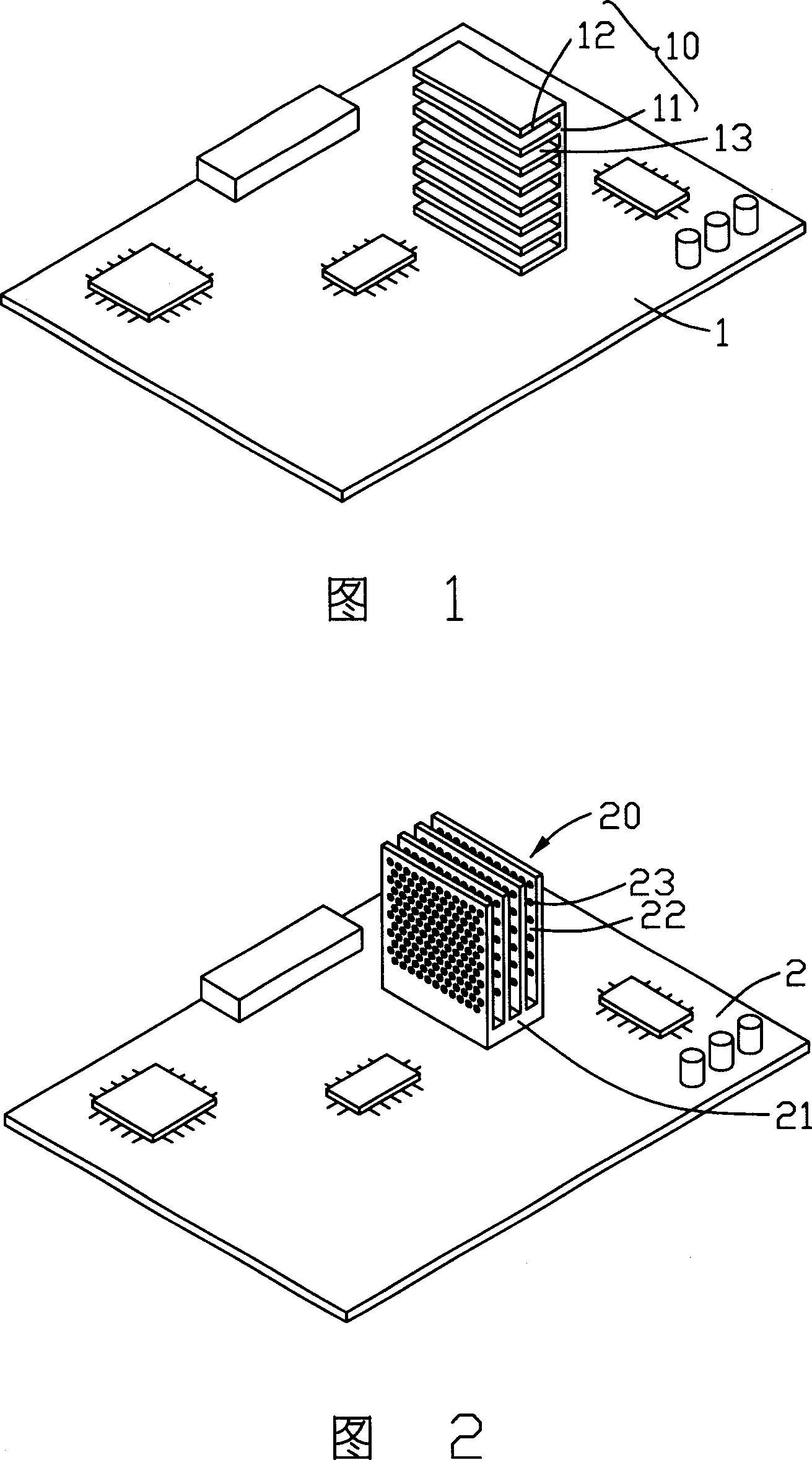
[0016] Please refer to FIG. 2 , which is a three-dimensional schematic view of the heat dissipation device 20 disclosed in the first embodiment of the present invention. The heat dissipation device 20 is disposed on an integrated circuit board 2 . The integrated circuit board 2 is a rectangular printed circuit board on which a plurality of electronic components are arranged.
[0017] The heat dissipation device 20 includes a heat conduction base 21 and a plurality of heat dissipation fins 22 . The heat conducting base 21 is disposed on the integrated circuit board 2 by welding. The plurality of cooling fins 22 are a group of flat plates arranged at intervals in parallel, and the plurality of cooling fins 22 are integrated with the heat conducting base 21, and each cooling fin 22 is arranged vertically to the heat conducting base 21. On each cooling fin 22 There are a plurality of ventilation holes 23 distributed in the array, and the ventilation holes 23 are circular through...
PUM
 Abstract
Description
Claims
Application Information
 - Generate Ideas
- Intellectual Property
- Life Sciences
- Materials
- Tech Scout
- Unparalleled Data Quality
- Higher Quality Content
- 60% Fewer Hallucinations
Browse by: Latest US Patents, China's latest patents, Technical Efficacy Thesaurus, Application Domain, Technology Topic, Popular Technical Reports.
© 2025 PatSnap. All rights reserved.Legal|Privacy policy|Modern Slavery Act Transparency Statement|Sitemap|About US| Contact US: help@patsnap.com