Supercharge Your Innovation With Domain-Expert AI Agents!

Circular knitting machine and electric motor

A circular knitting machine and electric motor technology, applied in the field of electric motors, can solve problems such as affecting the quality of knitted fabrics, endangering the working safety of the circular knitting machine, transmission interference, etc.

Active Publication Date: 2007-12-12
MEMMINGER IRO GMBH
View PDF5 Cites 2 Cited by
  • Summary
  • Abstract
  • Description
  • Claims
  • Application Information

AI Technical Summary

Problems solved by technology

Transmission disturbances and / or disturbances caused by transmission along long electrical cables can endanger the operational safety of the circular knitting machine and can negatively affect the quality of the knitted fabric

Method used


Image

  • Circular knitting machine and electric motor
  • Circular knitting machine and electric motor
  • Circular knitting machine and electric motor

Examples


Embodiment Construction

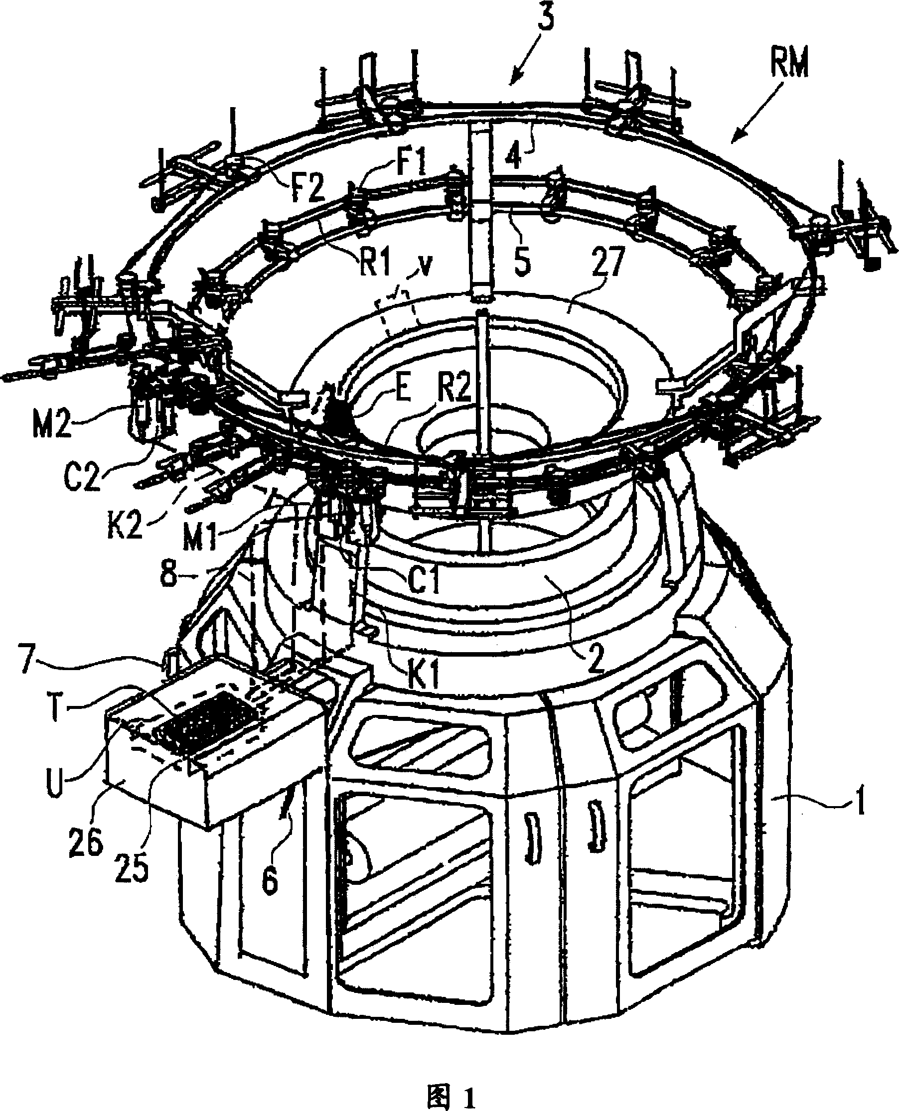
[0020] Fig. 1 schematically depicts a circular knitting machine RM represented only by basic elements. The circular knitting machine RM is situated on the ground with eg a polygonal base 1 and comprises a needle cylinder 2 on top of which a feeder carrying system 3 is arranged. Several yarn feeding devices F1, F2 of the same type or of different types are fixed on the carrier rings 4, 5 and integrated into the respective belt drives R1, R2. The belt drives driving the integrated yarn feeding devices F1, F2 are driven by at least one electric motor M1, M2.

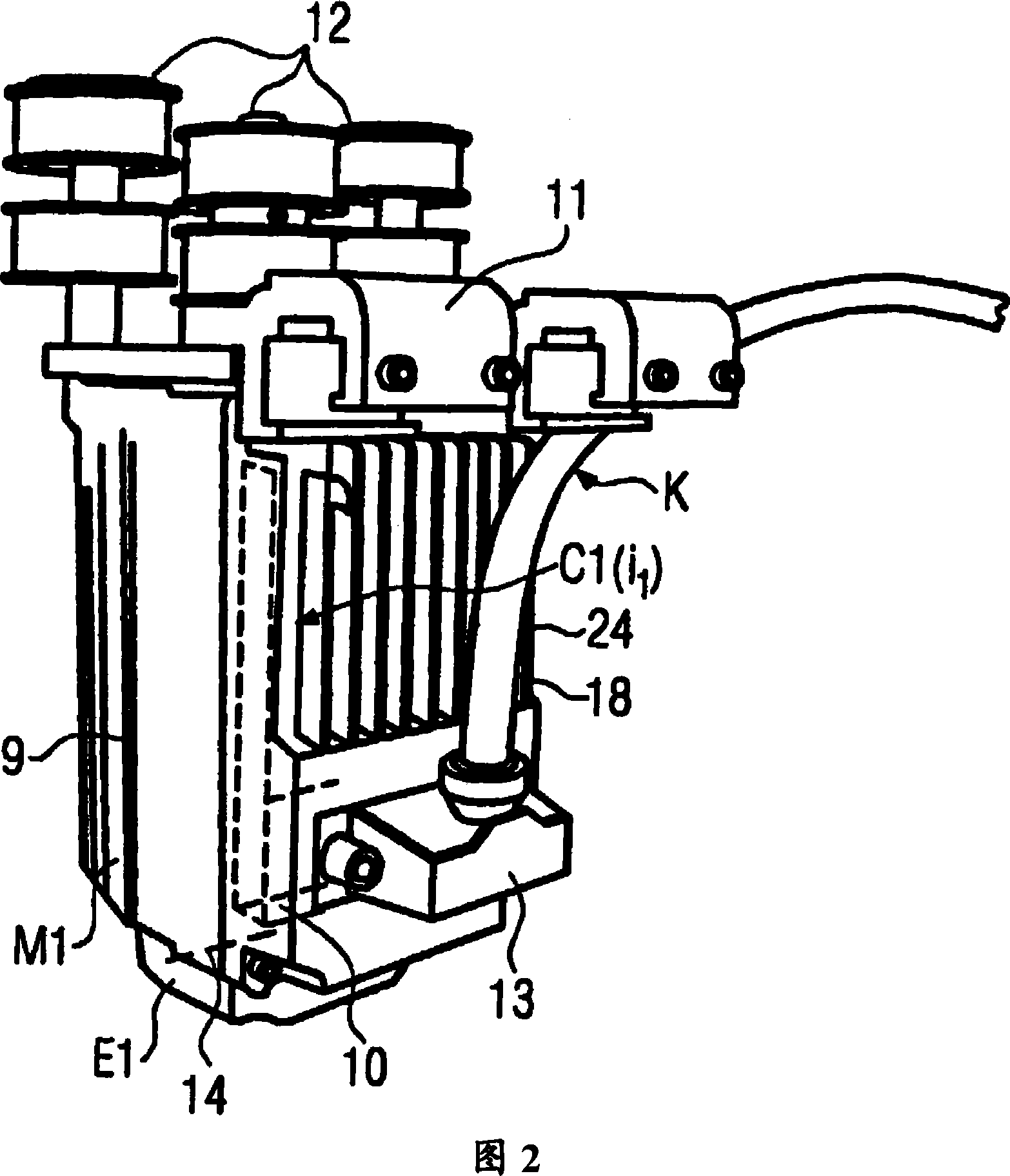
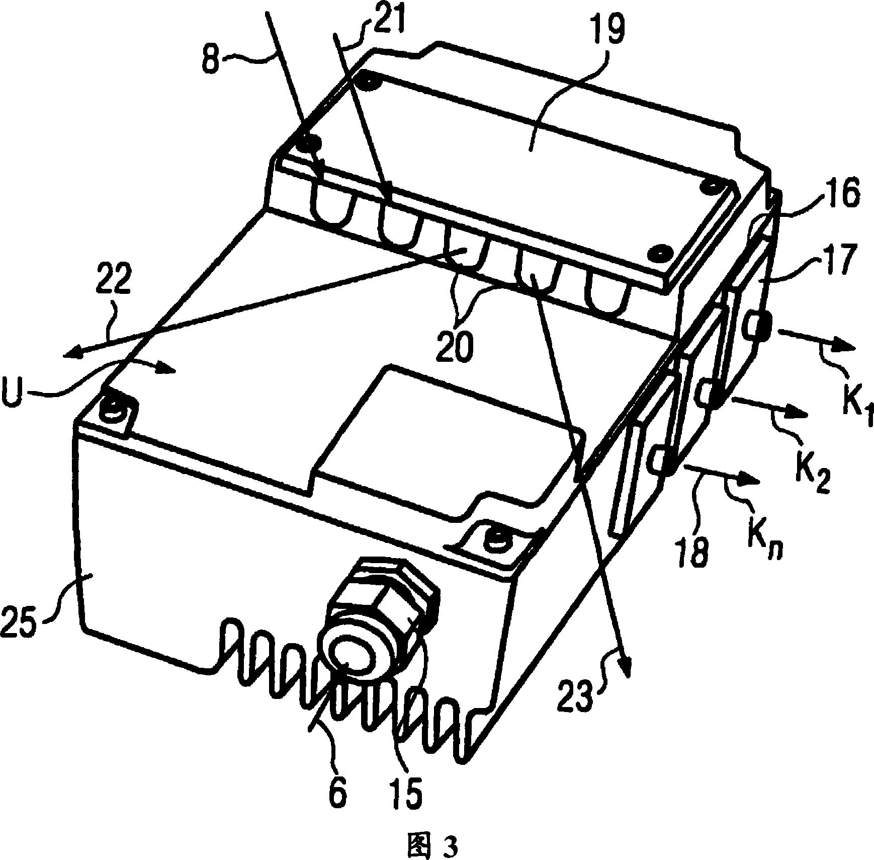
[0021] The motors M1 , M2 are for example permanent magnet motors, ie synchronous alternating current or AC motors. A speed controller C1, C2 with control circuit and power circuit (Fig. 2) is integrated into each motor. The electric motors M1, M2 are connected to the interface unit U via cable strands K1, K2. The interface unit U is generally used for all electric motors and is mounted, for example, on the base 1 of the...


PUM


Abstract

A motor speed controller is structurally integrated into an electric motor for a belt drive in a circular knitting machine. The motor speed controller is connected by means of a cable strand with an interface unit placed at the circular knitting machine. The motor speed controller directly controls the electric motor windings and receives in the cable strand only the motor supply current and a motor speed target value.

Description

technical field [0001] The invention relates to a circular knitting machine as described in the preamble of claim 1 and to an electric motor in the preamble of claim 9 . Background technique [0002] From D-72277 domstetten Memminger-Iro GmbH Technical Information Brochure No. 027.900.000.01 December 15, 2003 "Belt Drives for Motor Vehicles" it can be known that converters (inverters) are provided and the number of converters corresponds to the number of belts The number of electric motors in the drive, next to the base of the circular knitting machine stands in a housing on the bottom surface, the housing contains the machine controller. Each converter is connected to an electric motor via cable strands and converts the mains current into DC by means of a frequency conversion, taking into account a target value derived from the machine encoder signal. The speed signal or drive current signal corresponds to each target value. Machine encoders and control terminals for oper...

Claims


Application Information

Patent Timeline
IPC IPC(8): D04B15/48D04B9/02B65H51/22
CPCH02K11/0073D04B15/48D04B15/99H02K11/33
Inventor 斯迪格阿尔恩・布洛姆
Owner MEMMINGER IRO GMBH
Features
  • R&D
  • Intellectual Property
  • Life Sciences
  • Materials
  • Tech Scout
  • Unparalleled Data Quality
  • Higher Quality Content
  • 60% Fewer Hallucinations
Learn More