
Process of machining belt wheel for electromagnetic clutch

A technology of electromagnetic clutch and processing method, applied in the direction of belt/chain/gear, components with teeth, metal processing equipment, etc., can solve the problems of high cost, low production efficiency, pollution of the environment, etc., and achieve good balance and quality Lightweight and evenly distributed material

Inactive Publication Date: 2007-12-19
吴诗
View PDF0 Cites 30 Cited by
  • Summary
  • Abstract
  • Description
  • Claims
  • Application Information

AI Technical Summary

Problems solved by technology

Due to the hot forging method, it is easy to generate exhaust gas and dust, which will pollute the environment. In addition, it will also waste materials, resulting in low production efficiency and high cost.

Method used


Image

  • Process of machining belt wheel for electromagnetic clutch
  • Process of machining belt wheel for electromagnetic clutch
  • Process of machining belt wheel for electromagnetic clutch

Examples


Embodiment Construction

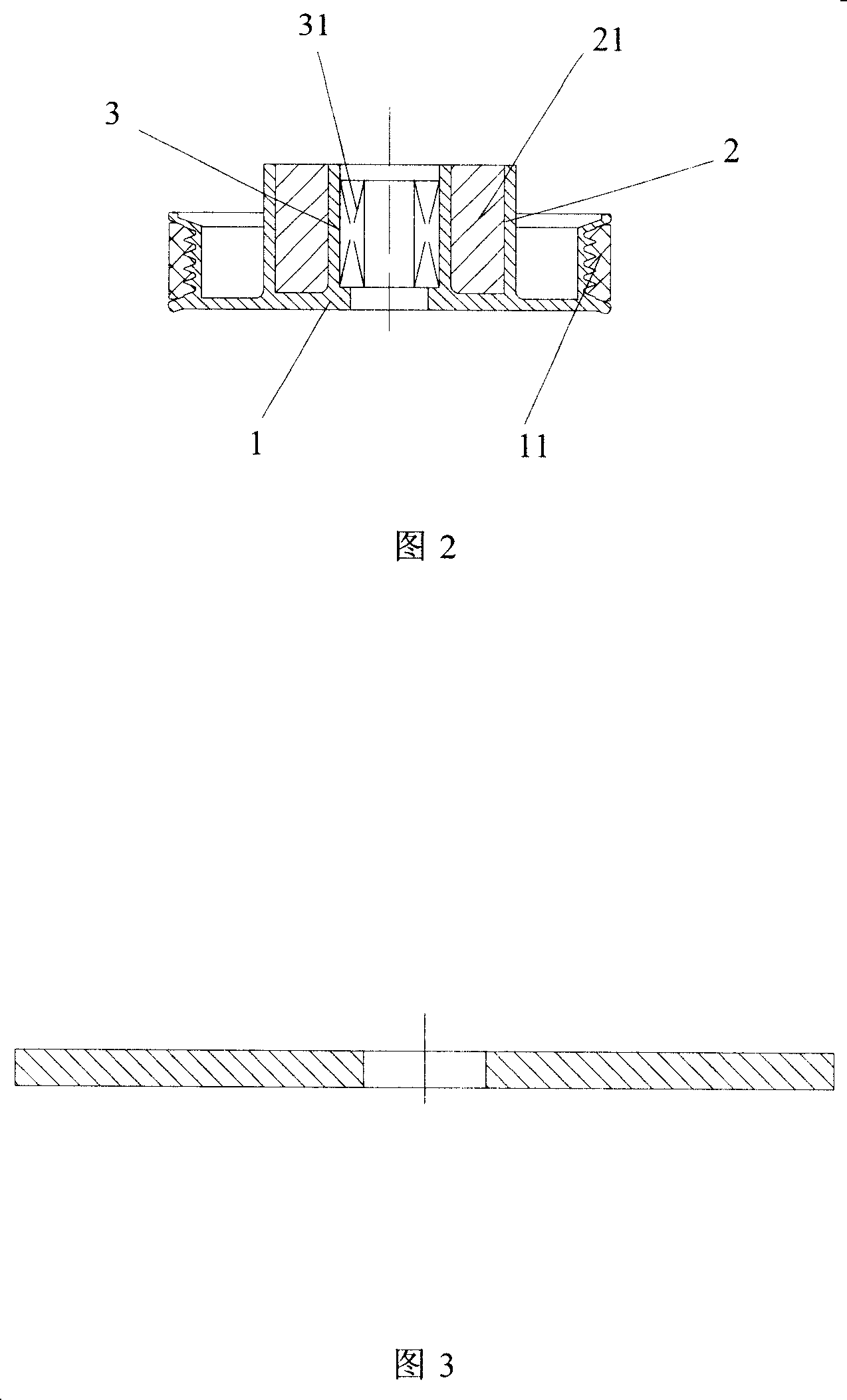
[0044] The present invention provides a processing method for a pulley of an electromagnetic clutch casing. As shown in FIG. 2 , the pulley of an electromagnetic clutch casing includes a pulley casing 1 , an electromagnetic coil slot 2 and a bearing chamber 3 . There is a belt groove 11 on the outer edge of the pulley housing 1, and the central hole of the pulley is used as a bearing chamber 3, in which a bearing 31 can be installed, and an electromagnetic coil groove 2 is arranged between the bearing chamber 3 and the pulley housing 1 for use in The coil 21 is installed.

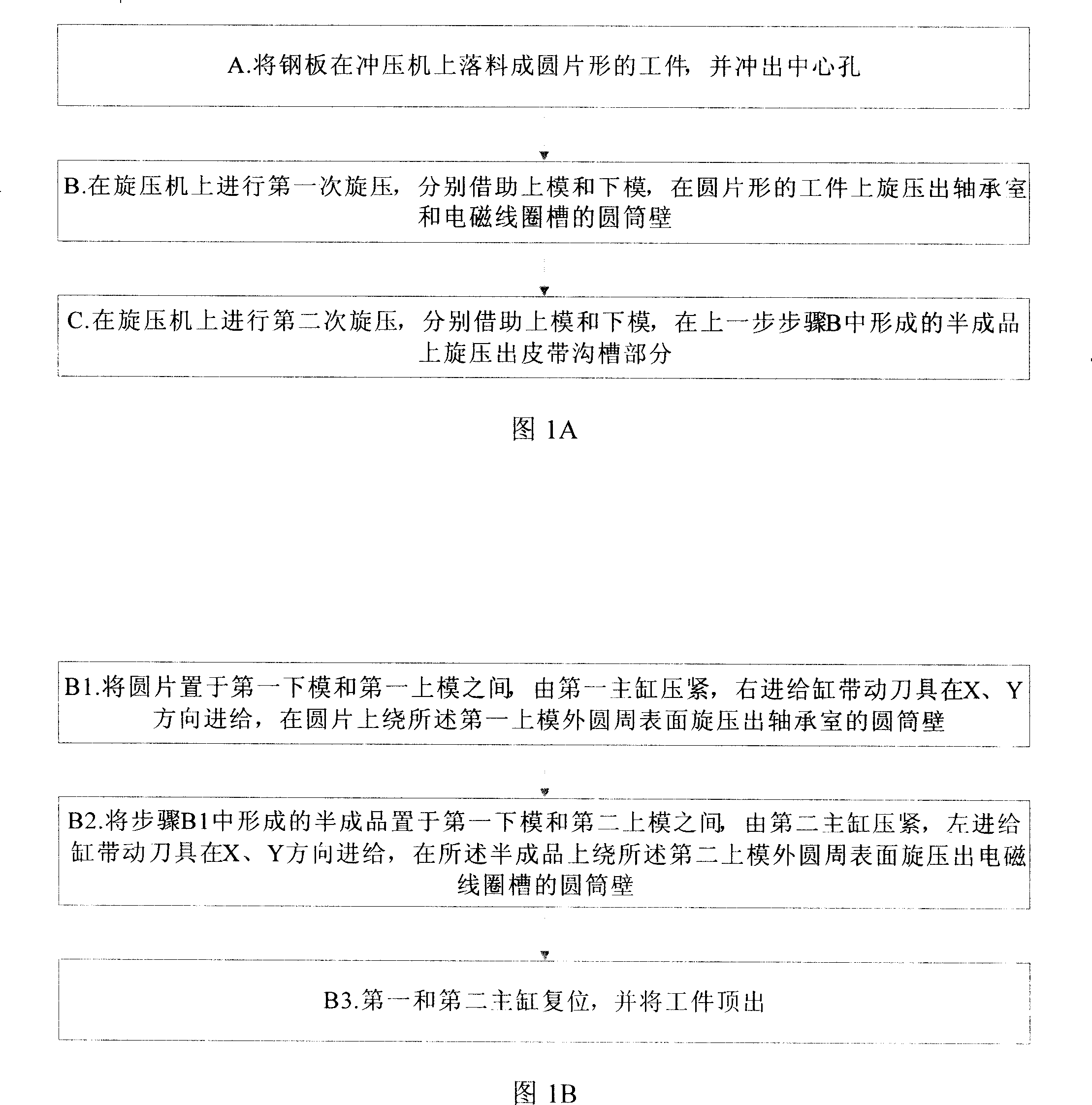
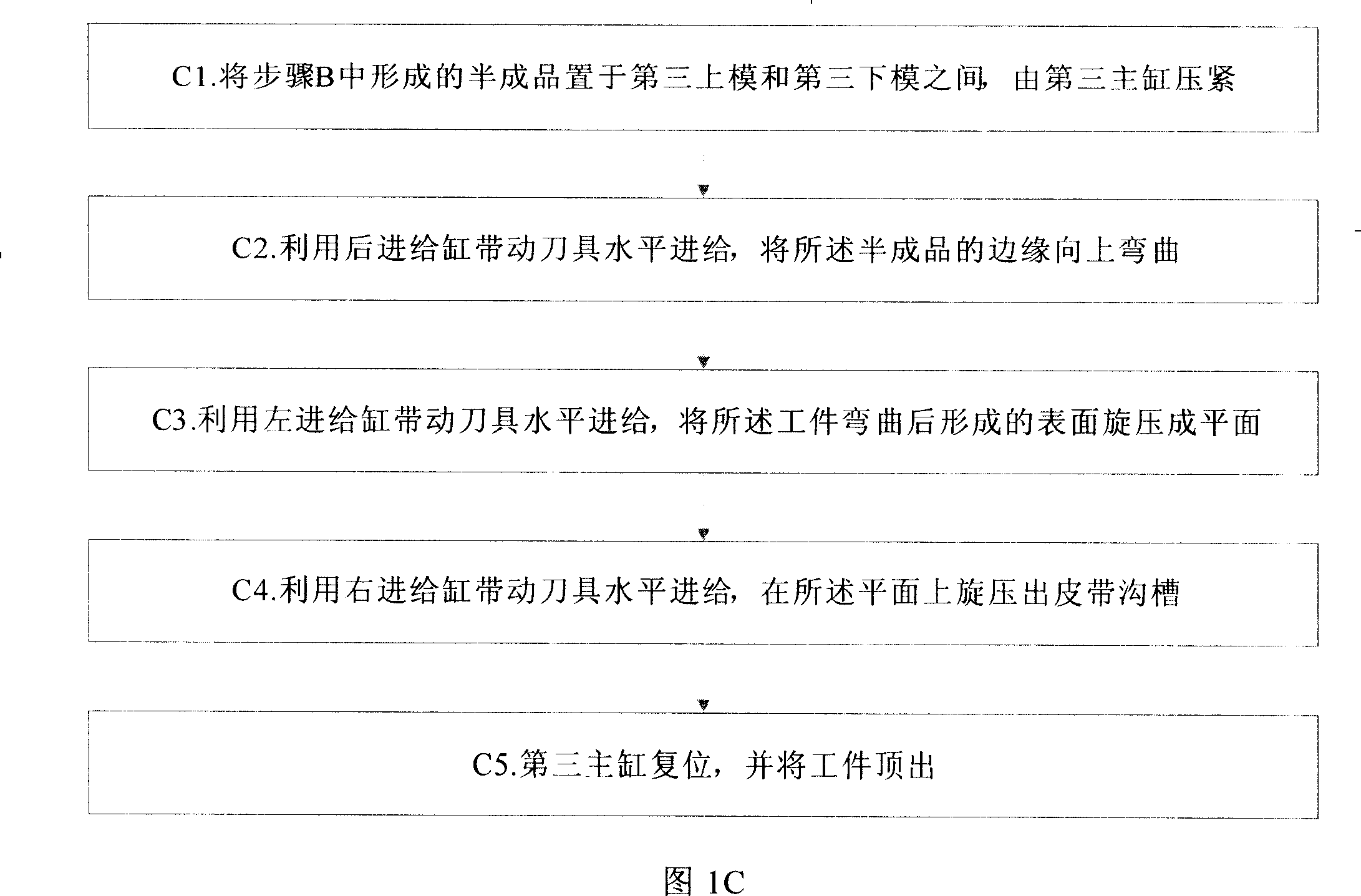
[0045] As shown in FIG. 1A to FIG. 1C , they are flowcharts of the present invention. The processing method of electromagnetic clutch shell belt pulley of the present invention, comprises the following steps:

[0046] A. Blanking the steel plate into a disc-shaped workpiece on the punching machine, and punching out the center hole 12;

[0047] B. Carry out the first spinning on the spinning machine, and s...


PUM


Abstract

The present invention relates to process of machining belt wheel for electromagnetic clutch. The belt wheel includes one casing, one bearing chamber, and one electromagnetic coil holder between the casing and the bearing chamber. The process of machining belt wheel includes the following steps: 1. punching steel plate material in a punch to form circular workpiece with central hole; 2. the first spinning in a spinning lathe with upper mold and lower mold to form the bearing chamber and the cylinder of the electromagnetic coil holder; and 3. the second spinning in the spinning lathe to form the belt slot in the casing. The process has environment friendship, high production efficiency and low production cost.

Description

technical field [0001] The invention relates to a processing method of a pulley, in particular to a processing method of an electromagnetic clutch shell pulley. Background technique [0002] As shown in Figure 1, the electromagnetic clutch housing pulley usually includes three parts: pulley housing 1, electromagnetic coil slot 2 and bearing chamber 3. There is a belt groove 11 on the outer edge of the pulley housing 1, and the central hole of the pulley is used as a bearing chamber 3, in which a bearing can be installed, and an electromagnetic coil groove 2 is provided between the bearing chamber 3 and the pulley housing 1 for Install the coil. The traditional processing technology usually uses 10# steel, first hot forging, then steel die forging, and finally using CNC machine tools for multiple turning processes. Due to the hot forging method, exhaust gas and dust are easily generated, which pollutes the environment. In addition, materials are wasted, the production effic...

Claims


Application Information

Patent Timeline
IPC IPC(8): B21D53/26B21D35/00B21D28/24B21D22/14B21D37/10B23P15/14F16H55/36
Inventor 吴德俊
Owner 吴诗
Learn More