Mother matrix surface detecting method and device, mother matrix class detecting device and print device

A detection device and detection method technology, applied in the direction of stencil printing equipment, printing, printing technology, etc., can solve the problems of increased number of color sensors, increased cost, mechanical layout constraints, etc., to achieve cost reduction, cost reduction, and constraints The effect of halving

Inactive Publication Date: 2007-12-19
RISO KAGAKU CORP
View PDF6 Cites 2 Cited by
  • Summary
  • Abstract
  • Description
  • Claims
  • Application Information

AI Technical Summary

Problems solved by technology

Therefore, as with the technology described in Patent Document 1, the number of color sensors used increases, and at the same time, the cost becomes twice that of using one color sensor, and the cost inevitably increases.
In addition, because the mechanical layout (mechanical layout) used for detection must also consider two places, resulting in constraints on the mechanical layout

Method used


Image

  • Mother matrix surface detecting method and device, mother matrix class detecting device and print device
  • Mother matrix surface detecting method and device, mother matrix class detecting device and print device
  • Mother matrix surface detecting method and device, mother matrix class detecting device and print device

Examples


no. 1 approach

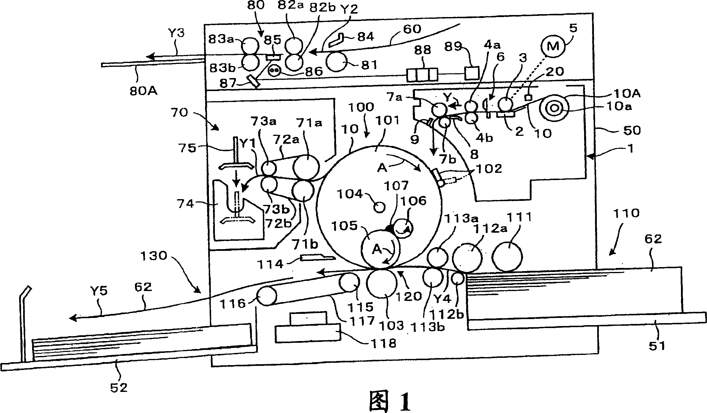
A first embodiment will be described with reference to FIGS. 1 to 6 . First, referring to FIG. 1 , an example of the overall configuration of a stencil printing apparatus as a digital thermal stencil plate-making apparatus and a printing apparatus of the plate-making apparatus according to the first embodiment will be described.

In FIG. 1 , reference numeral 50 denotes an apparatus body constituting a frame of the stencil printing apparatus. On the top of the device body 50, the part represented by the mark 80 is the original reading device, and the part represented by the mark 1 below it is the plate making device with the master surface / backside detection device of the present invention, and the left side is marked by the mark 100. The part shown is a printing cylinder device equipped with a printing cylinder 101 provided with a porous cylindrical plate shell on its outer periphery, the part indicated by a mark 70 on the left is a typesetting device, and the lower part of th...

no. 2 approach

Referring to FIG. 7 and FIG. 8, a master type detecting device 32 (indicated by a chain line in FIG. 7) of a second embodiment will be described.

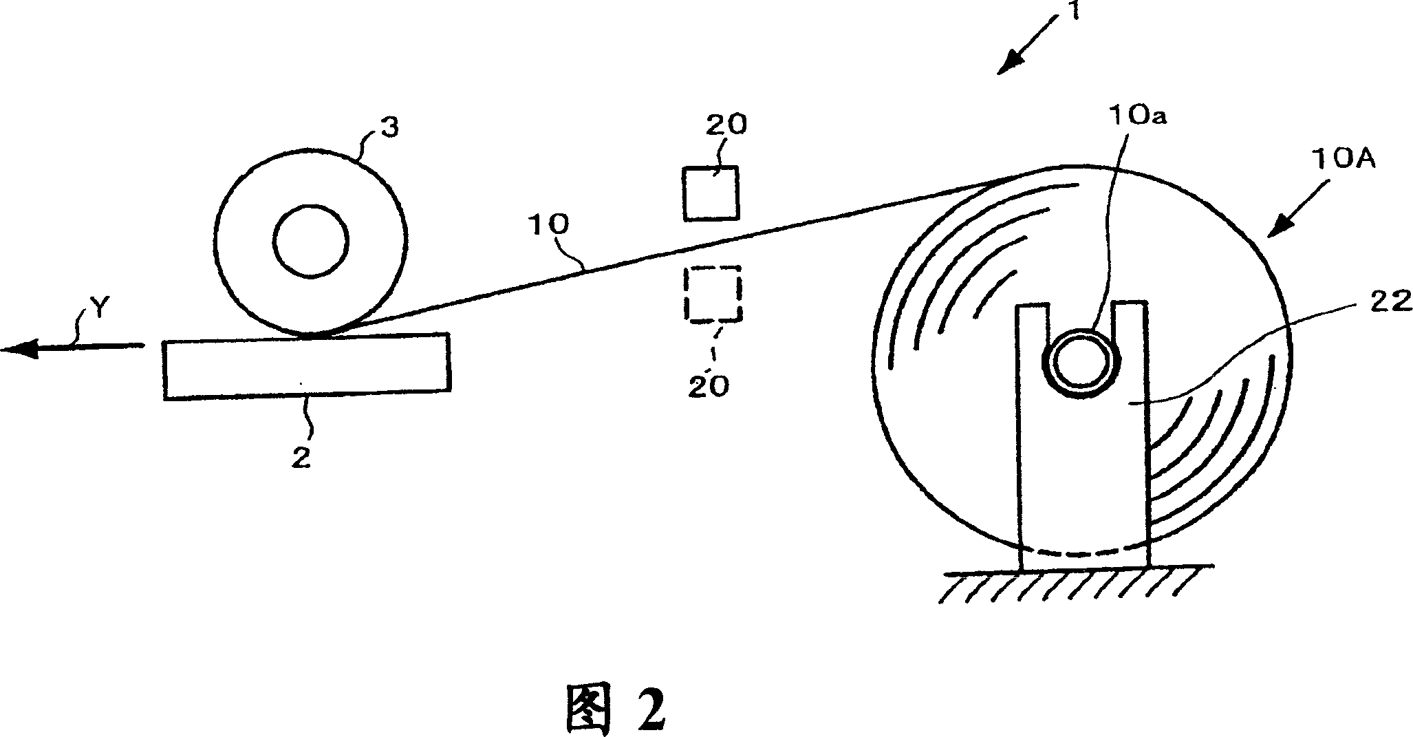
The master type detection device 32 is mainly composed of the following parts, namely: as shown in the two figures, as a coloring portion 10C shown in a sand pattern in the figure of the coloring master 10B used as an example of a colored master for detection. The photosensor 30 of the color detecting part; the judging part 36 for judging the type of the master 10 according to the detection voltage as the output signal of the photosensor 30.

[0070]

The colored master 10B used in this embodiment is compared with the master 10 of the three-layer structure shown in FIG. The type of version. That is, the material configuration and the like of the coloring master 10B are the same as those of the master 10 except for the above-mentioned differences. As a method of coloring the porous fibrous membrane 13 in blue, for example, dyeing t...

no. 3 approach

Referring to FIG. 8 and FIG. 9 , a master surface / back surface detecting device 37 (indicated by a dotted line in FIG. 9 ) of a third embodiment will be described. Incidentally, the master surface / backside detecting means 37 can detect the surface / backside of the master to be colored, and can detect the kind of the colored master, and should be called the masterface / backside, type detecting means.

The master surface / backside detection device 37 of the third embodiment is equivalent to adding the master type of the second embodiment shown in FIG. 7 to the master surface / backside detection device 23 of the first embodiment shown in FIG. The device after the structure / function of the main part of the control structure unique to the detection device 32 . That is, the main difference between the master surface / backside detection device 37 of this embodiment and the master surface / backside detection device 23 shown in FIG. In the sensor 20 , a judging part 36 is used instead of the...


PUM


Abstract

The present invention reduces the number of reflection-type optical transducer to one, reduces the cost and reduces the restriction in the mechanical layout, and it can detect the surface/back side of the master mask to prevent the master mask setting error. The master mask surface/back side detecting device (23) is provided with the following components: a single optical sensor (20) which scans and detects the surface of back side of the master mask (10); a master mask delivering motor (5) which movers the master mask (10) relative to the optical sensor (20) and a guide roller (3); a special hardware 24 which is inputted with the detected electric tension that is detected by the optical sensor (20) and is relative to the surface or back side of the master mask (10); and a judging component which controls the action of the thermal head (2) by the master mask delivering motor (5), a LCD displaying part (47) of the operator panel (40) and the plate making control part (21), and at the same time the judging component judges the surface/back side of the master mask (10) according to the margin of the detected electric tension inputted by the special hardware (24).

Description

technical field [0001] The present invention relates to a printing device including a master surface / backside detection method, a master surface / backside detection device, a master type detection device, a stencil printing device and the like. Background technique [0002] Currently, digital thermal stencil printing is known as a simple printing method. This is based on the image data read from the original image or the image information output by a computer such as a personal computer. A heat-sensitive stencil master (hereinafter simply referred to as "master") as a printing plate is melted and perforated by a thermal head or the like, and the plate-making A device in which the completed master master roll is printed on the outer peripheral surface of a printing cylinder having a porous cylindrical plate shell provided on its outer periphery. Hereinafter, the plate case is simply referred to as a "print cylinder". Ink is supplied to the inner peripheral surface of th...

Claims


Application Information

Patent Timeline
Patent Type & Authority Applications(China)
IPC IPC(8): B41N1/24B41L13/04B41L13/14B41C1/055
Inventor 斋藤和幸橘隆史
Owner RISO KAGAKU CORP
Why Eureka
Try Eureka