

Band spreading coding method and device and decode method and device
A technology of frequency band extension and encoding method, applied in the fields of frequency band extension encoding method and device, decoding method and device, capable of solving problems such as low sound quality and large distortion
- Summary
- Abstract
- Description
- Claims
- Application Information
AI Technical Summary
Problems solved by technology
Method used
Image

Examples
Embodiment 1
[0120] Embodiment 1: a first type of frequency band extension coding device.
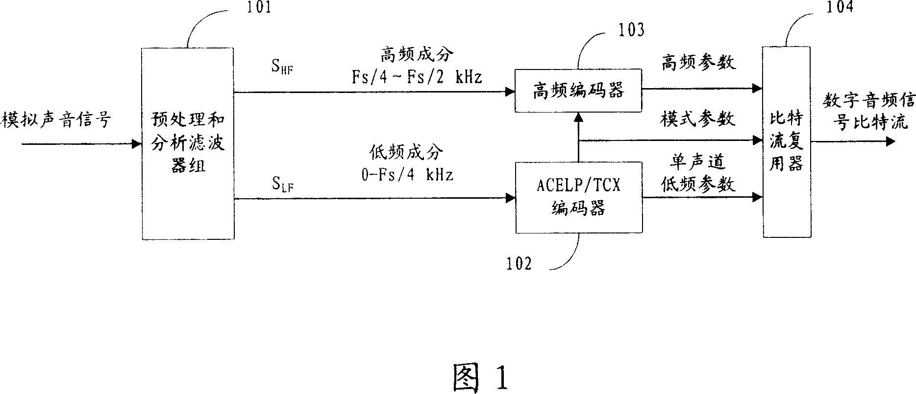
[0121] A schematic diagram of the structure of the frequency band extension encoding device of this embodiment is shown in FIG. 5 . The frequency band extension coding method of the present invention includes a time-varying prediction analysis module 501 , a signal type analysis module 502 , a spectrum parameter encoding module 503 , a time-varying prediction synthesis module 504 and a time-domain adaptive gain adjustment parameter extraction module 505 .
[0122] The time-varying prediction analysis module 501 is used to receive the original high-frequency time-domain signal output by the preprocessing and analysis filter bank 101, and divide the received original high-frequency time-domain signal according to the analysis result from the signal type analysis module 502 It is one or more predicted frames, and the predicted frame is a group of time-domain signal samples, which is the unit of linear ...
Embodiment 2
[0204] Embodiment 2: a second type of frequency band extension coding device.
[0205] The structural diagram of the frequency band extension coding device of this embodiment is shown in FIG. 11 . Compared with FIG. 5 , a coding mode selection module 507 is added, and other modules are identical to those with the same name in FIG. 5 . The encoding mode selection module 507 is used to receive the low-frequency encoding mode information and the low-frequency excitation signal or spectrum from the low-frequency encoder, and perform processing according to the preset high-frequency encoding mode, and the preset high-frequency encoding mode is divided into mode 1 and mode 2. Mode 1 performs both frequency domain adjustment and time domain adjustment on the TCX frame low-frequency excitation spectrum output by the low-frequency encoder or the low-frequency time-domain excitation signal of the ACELP frame; while mode 2 performs frequency domain adjustment on the TCX frame low-frequenc...
Embodiment 3
[0212] Embodiment 3: a first type of frequency band extension decoding device.
[0213] The device in this embodiment is a decoding device corresponding to the encoding device in Embodiment 2. Its structural diagram is shown in FIG. and time-varying prediction synthesis module 1204 .
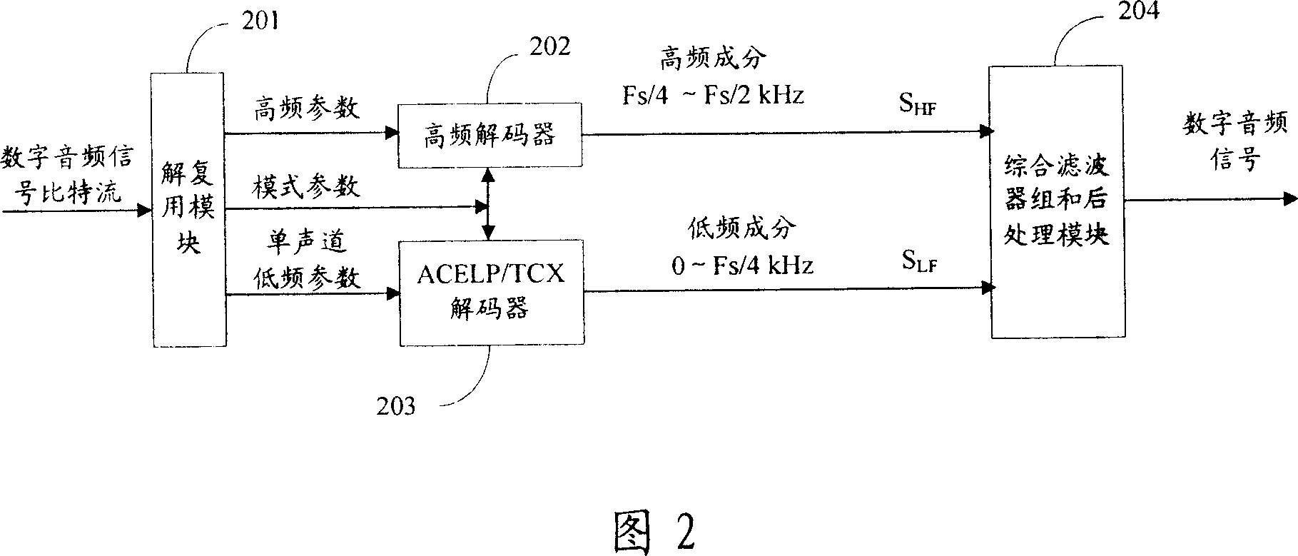
[0214] The high-frequency decoding mode selection module 1201 first selects the high-frequency decoding mode. The high-frequency decoding mode corresponds to the high-frequency encoding mode in Embodiment 2, including mode 1 and mode 2. The selection method is the same as that of the encoding end. When mode 1 is selected, the low-frequency excitation spectrum of the TCX frame obtained from the TCX decoder is output to the spectral parameter decoding module 1202, or the low-frequency excitation signal of the ACELP frame obtained from the ACELP decoder is transformed by DFT to obtain the low-frequency excitation of the ACELP frame spectrum, and output the low-frequency excitation spectrum of the ...
PUM
 Abstract
Description
Claims
Application Information