Semiconductor package and its manufacturing method
A semiconductor and packaging technology, applied in the field of semiconductor packaging and its manufacturing method, can solve the problems of restricting the use of electronic products, being unable to provide electronic products with electrical functions, and providing
- Summary
- Abstract
- Description
- Claims
- Application Information
AI Technical Summary
Problems solved by technology
Method used
Image
Examples
Embodiment 1
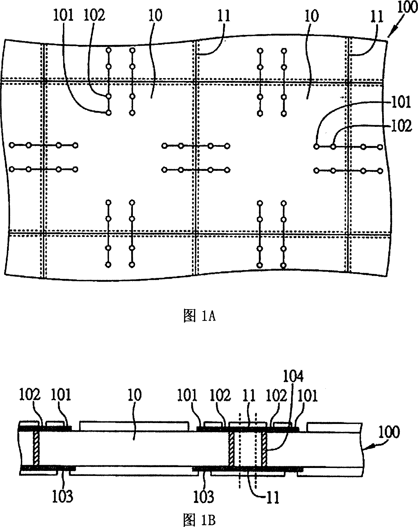
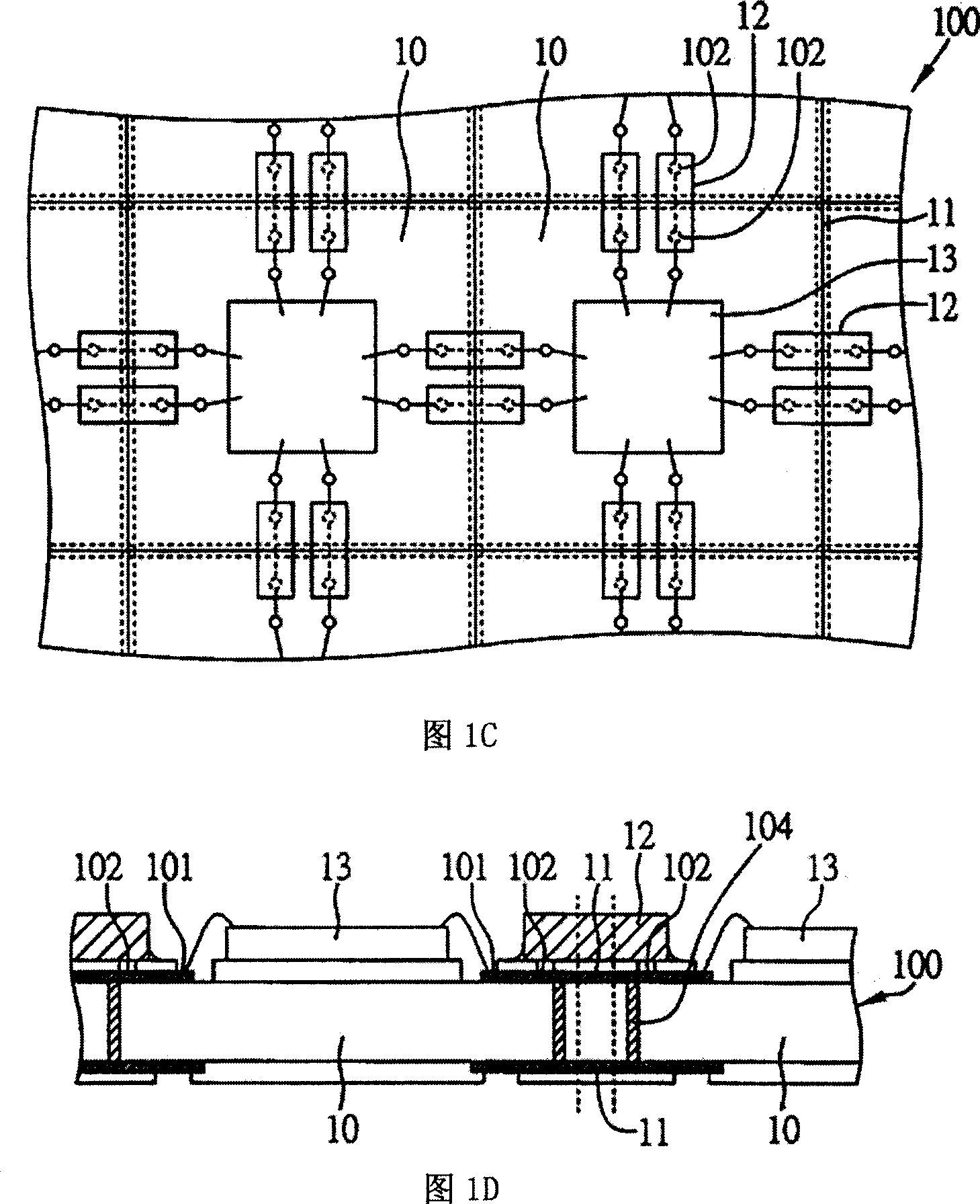
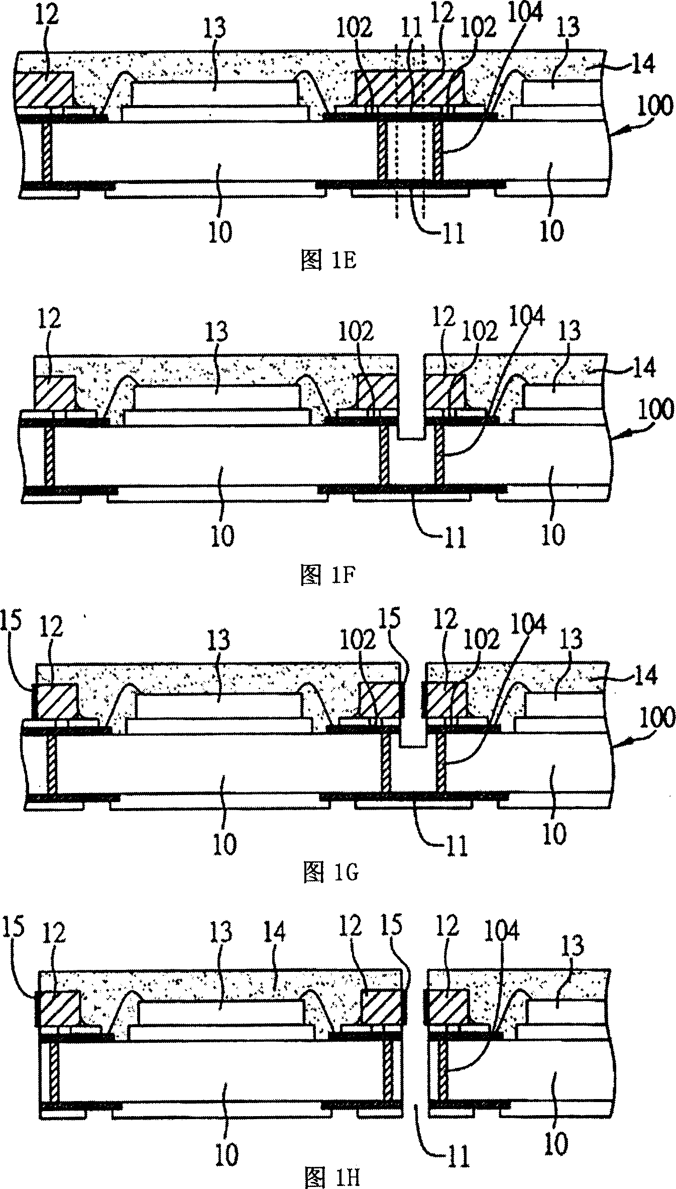
[0024] 1A to 1H are schematic diagrams of Embodiment 1 of the semiconductor package and its manufacturing method of the present invention.
[0025] As shown in Figure 1A, at first, provide a chip carrier module sheet with a plurality of chip carriers, each chip carrier is provided with a plurality of electrical connection points, refer to Figure 1B at the same time, it is the chip carrier module sheet corresponding to Figure 1A The cross-sectional schematic diagram, in this embodiment, the chip carrier module is a substrate module 100, each of the chip carriers is a thin ball grid array (TFBGA) or land grid array (LGA) substrate 10, each of the substrate 10 Divided by a plurality of transverse and vertical cutting lines (as shown by dotted lines), at the same time at the transverse and vertical cutting lines, electroplating bus lines 11 are formed on the upper and lower surfaces of the corresponding substrate module sheet 100, so that the electroplating bus lines 11 The ring i...
Embodiment 2
[0033] 2A to 2E are schematic diagrams of Embodiment 2 of the semiconductor package and its manufacturing method of the present invention. This embodiment is substantially the same as the above embodiment, so the same components will not be described again.
[0034] As shown in FIG. 2A , first provide a substrate module sheet 200 with a plurality of substrates 20, each of the substrates 20 is provided with an electroplating bus 21 between the upper and lower surfaces, and the electroplating bus 21 is extended and electrically connected to the substrate. The surface circuit structure of the sheet 20, wherein a plurality of electrical connection points such as first electrical connection pads 201 and second electrical connection pads 202 are provided on the upper surface of each of the substrates 20, and on the upper surface of the substrate 20 The lower surface is provided with a third electrical connection pad 203, the first electrical connection pad 201 can be electrically con...
Embodiment 3
[0040] FIG. 3 is a schematic diagram of a substrate module used in Embodiment 3 of the semiconductor package and its manufacturing method of the present invention.
[0041] As shown in the figure, this embodiment is substantially the same as the above-mentioned embodiment, the main difference is that the substrate module sheet 300 has a plurality of substrates 30, and the upper and lower surfaces of each substrate 30 are provided with an electroplating bus 31, and The upper surface of each of the substrates 30 is provided with a plurality of electrical connection points such as first electrical connection pads 301 and second electrical connection pads 302, wherein the second electrical connection pads 302 between the adjacent substrates 30 connected together, and the first and second electrical connection pads 301 , 302 are electrically connected to the electroplating bus 31 .
[0042] Subsequent methods such as the above-mentioned embodiments can be used to connect and electr...
PUM
 Abstract
Description
Claims
Application Information
 - R&D
- Intellectual Property
- Life Sciences
- Materials
- Tech Scout
- Unparalleled Data Quality
- Higher Quality Content
- 60% Fewer Hallucinations
Browse by: Latest US Patents, China's latest patents, Technical Efficacy Thesaurus, Application Domain, Technology Topic, Popular Technical Reports.
© 2025 PatSnap. All rights reserved.Legal|Privacy policy|Modern Slavery Act Transparency Statement|Sitemap|About US| Contact US: help@patsnap.com


