Carrying structure for electron element
A technology of electronic components and load-carrying structures, applied in the field of load-bearing structures of electronic components, can solve problems that do not conform to the development trend of thin and short semiconductor packages, reduce the flexibility of circuit board surface layout, and limit the number of passive component layouts, etc., to achieve Reduce reliability risks, improve quality and reliability, and improve electrical performance
- Summary
- Abstract
- Description
- Claims
- Application Information
AI Technical Summary
Problems solved by technology
Method used
Image
Examples
Embodiment 1
[0024] The load-bearing structure of the electronic component in this embodiment 1 includes: at least one support plate, the support plate is provided with at least one opening; at least one electronic component has an active surface and a non-active surface, and is arranged in the corresponding opening of the support plate; and at least An adhesive layer is formed on the surface of the support plate, wherein the adhesive layer partially fills the gap between the opening and the electronic component, so that the electronic component is fixed in the opening of the support plate.
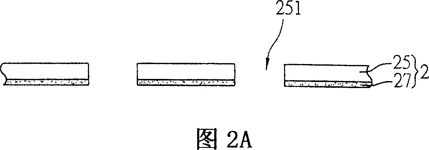
[0025]2A and 2B are schematic diagrams of the carrying structure of the electronic components of the present invention. As shown in the figure, the supporting structure 2 is provided with a support plate 25 , and the support plate 25 is provided with at least one opening 251 , wherein an adhesive layer 27 is formed on the surface of the support plate 25 . In the present embodiment 1, the carrying stru...
Embodiment 2
[0030] The carrying structure of the electronic component in the second embodiment includes: at least one first support plate and a second support plate, the first support plate and the second support plate are provided with at least one opening; at least one adhesive layer is formed on the first Between the support plate and the second support plate and at least one electronic component has an active surface and a non-active surface, which are arranged in corresponding openings of the first support plate and the second support plate. Wherein the adhesive layer partially fills the gap between the openings of the first support plate and the second support plate and the electronic component, so that the electronic component is fixed in the openings of the first support plate and the second support plate.
[0031] FIG. 3A is a schematic diagram of Embodiment 2 of the carrying structure of the electronic component of the present invention. The biggest difference between Embodiment...
Embodiment 3
[0037] 4A to 4C are schematic views of Embodiment 3 of the carrying structure of the electronic component of the present invention, wherein the same or similar components as those of the above embodiment are represented by the same or similar component symbols.
[0038] As shown in FIG. 4A , the electronic component carrying structure includes: a support plate 25 , at least one electronic component 23 and an adhesive layer 27 formed on the surface of the support plate.
[0039] The support plate 25 is provided with at least one opening 251 , wherein, although the supporting structure 2 is shown as a two-layer structure including the support plate 25 and the adhesive layer 27 in the drawing, it is not limited thereto.
[0040] The electronic component 23 has an active surface and a non-active surface. In Embodiment 3, the active surface of the electronic component 23 is located on the upper surface, and the non-active surface of the electronic component 23 is located on the lowe...
PUM
 Abstract
Description
Claims
Application Information
 - R&D
- Intellectual Property
- Life Sciences
- Materials
- Tech Scout
- Unparalleled Data Quality
- Higher Quality Content
- 60% Fewer Hallucinations
Browse by: Latest US Patents, China's latest patents, Technical Efficacy Thesaurus, Application Domain, Technology Topic, Popular Technical Reports.
© 2025 PatSnap. All rights reserved.Legal|Privacy policy|Modern Slavery Act Transparency Statement|Sitemap|About US| Contact US: help@patsnap.com


