
X-ray tube

An X-ray tube and X-ray technology, applied in the field of fixed anode type X-ray tubes, can solve the problems of reducing the heat load of the anode target, increasing the cost, poor heat dissipation characteristics, etc.

Inactive Publication Date: 2007-12-19
KK TOSHIBA +1
View PDF1 Cites 14 Cited by
  • Summary
  • Abstract
  • Description
  • Claims
  • Application Information

AI Technical Summary

Problems solved by technology

When a filter is required, maintenance and management are troublesome and cost increases
[0009] In addition, although the conventional forced air-cooled X-ray tubes do not have the same problems as the aforementioned insulating oil-immersed and forced liquid-cooled X-ray tubes, due to the heat transfer from the anode support to the packaging material with low thermal conductivity, Dissipates heat, so heat dissipation characteristics are poor
Therefore, there is a problem that the thermal load on the anode target cannot be sufficiently reduced.
Therefore, there is a problem that the temperature of the packaging material rises, and the insulation properties of the packaging material deteriorate compared to earlier

Method used


Image

  • X-ray tube
  • X-ray tube
  • X-ray tube

Examples


Embodiment Construction

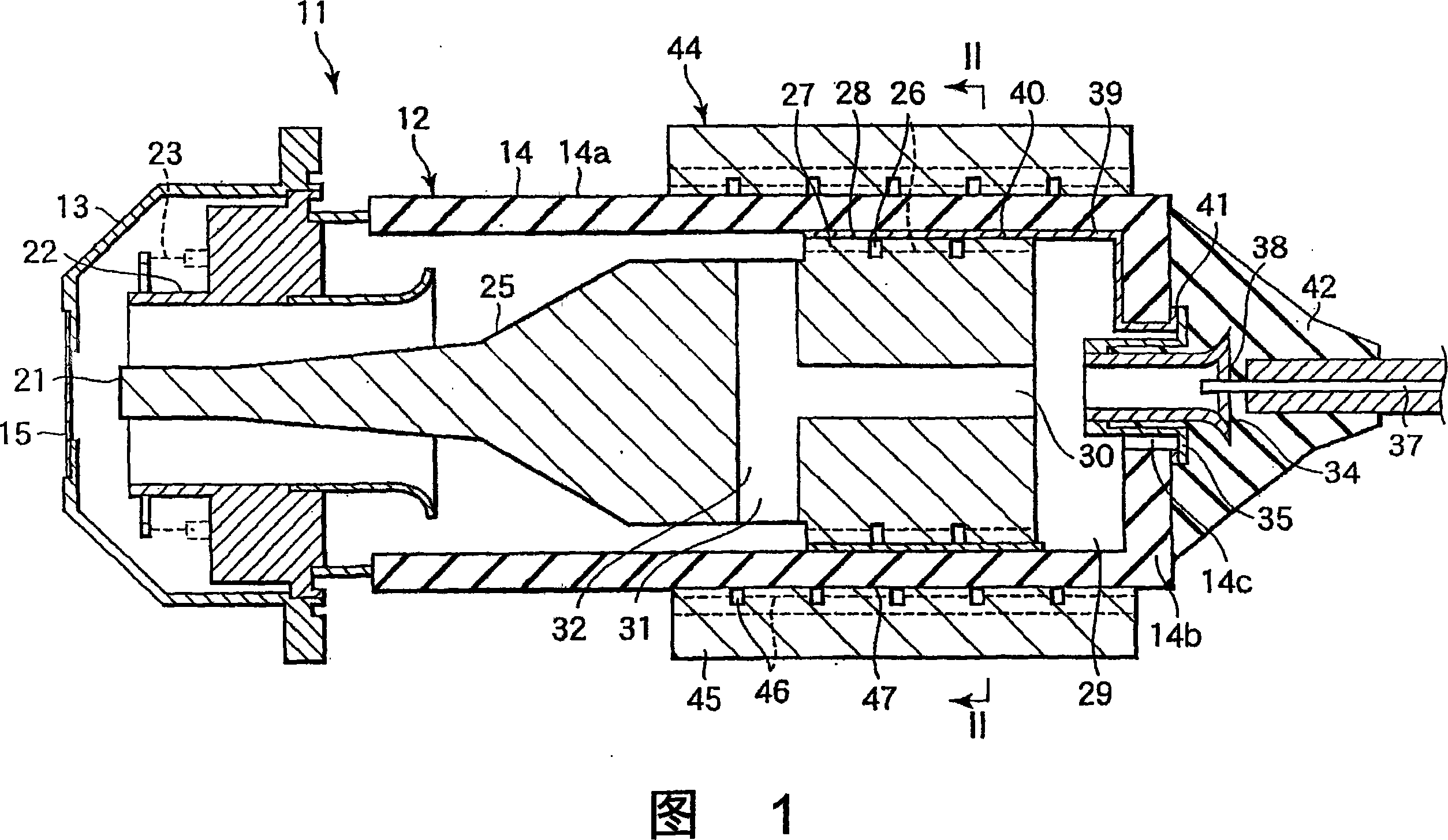
[0026] Hereinafter, a fixed anode type X-ray tube according to an embodiment of the present invention will be described with reference to the drawings.

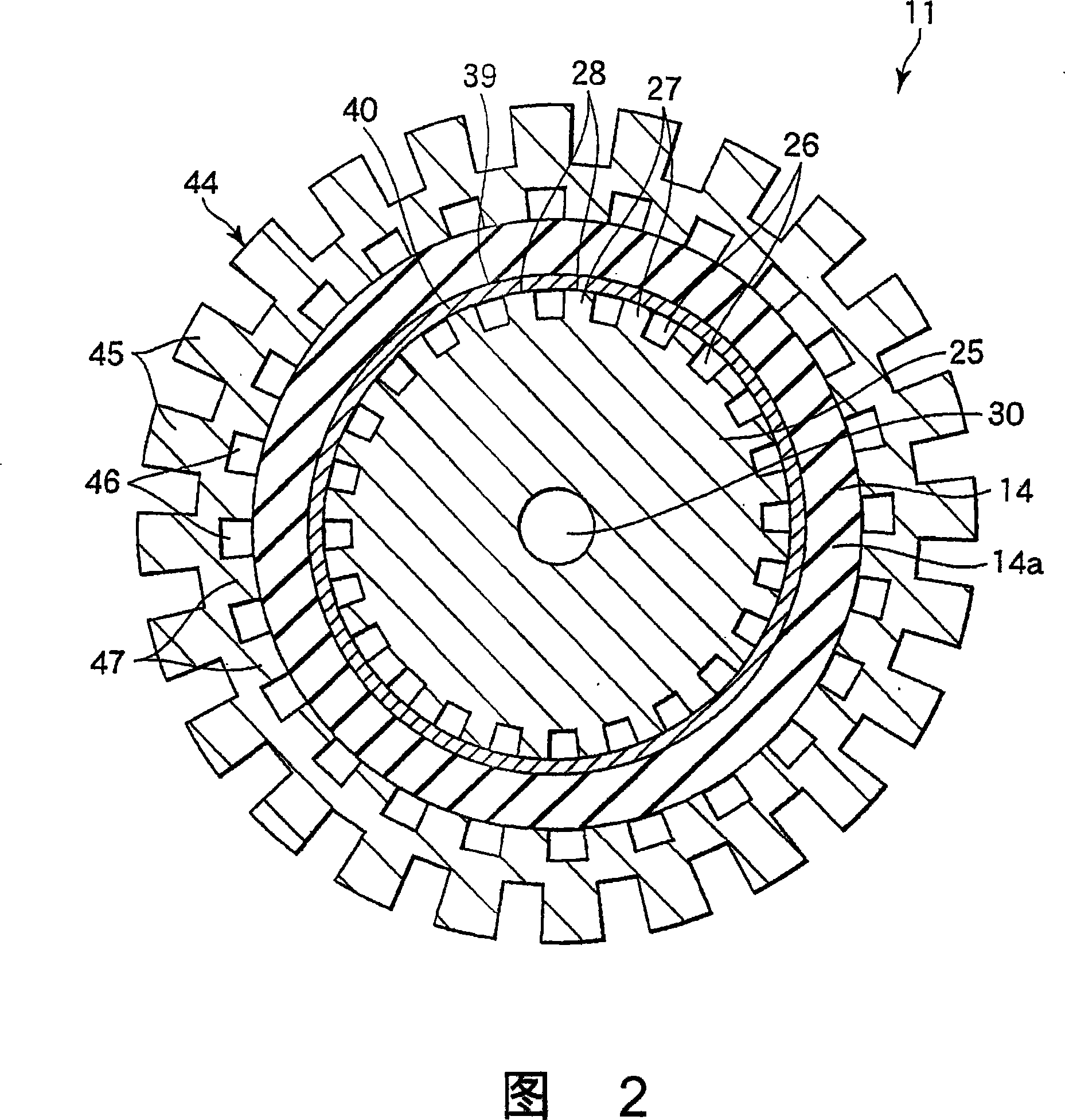
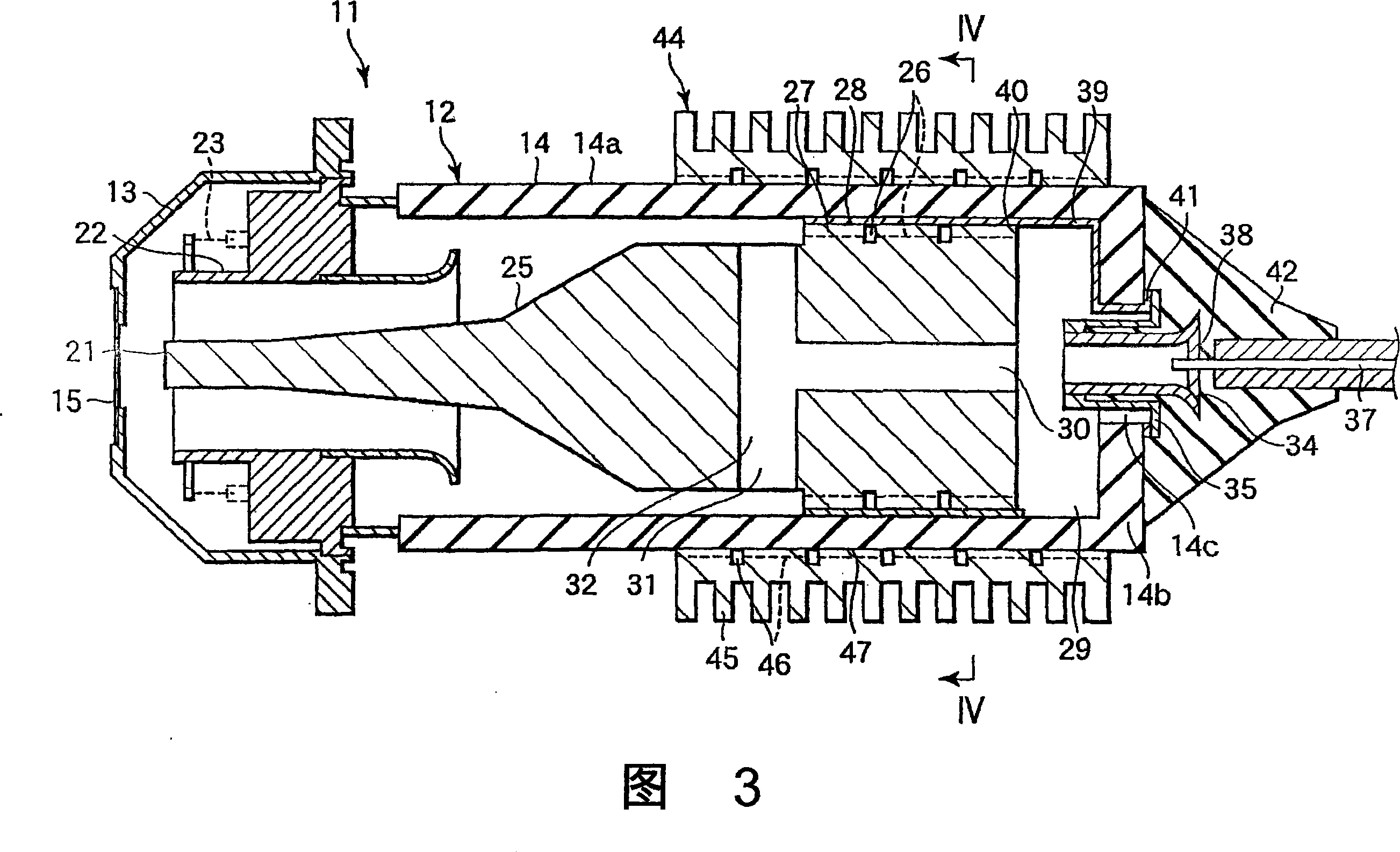
[0027] 1 and 2 show a fixed anode type X-ray tube 11 as an X-ray tube. The X-ray tube 11 has a casing 12 that keeps the inside in a vacuum state. The casing 12 is formed by combining a first casing 13 made of metal on one end side along the axial direction of the tube axis of the X-ray tube 11 and a second casing 14 on the other end side constituting the insulating portion.

[0028] The first housing 13 is formed in a cap shape (tubular shape) whose outer diameter at the front end gradually decreases. The front end surface of the first housing 13 is formed as a flat surface. An output window 15 that transmits X-rays is provided on the flat portion. The output window 15 is made of a material that reduces the attenuation of X-rays, such as beryllium (Be), and has a thickness of about several tens to several hundreds of μm.

...


PUM


Abstract

Disclosed is an x-ray tube (11) wherein heat dissipation characteristics are improved and insulation characteristics are secured for a long time. In the x-ray tube (11), a supporting body (25) supports an anode target (21) at one end and is provided with a joint portion (28) on the outer surface of the other end portion. The joint portion (28) is joined with the inner surface of a cylinder portion (14a) of a second envelope (14) for improving heat transfer from the supporting body (25) to the second envelope (14) through the joint portion (28). A terminal (38) for supplying a voltage to the anode target (21) is provided on the end face (14b) of the other end portion of the second envelope (14). By arranging the terminal (38) away from the joint portion (28), the temperature of an insulating material (42) for insulation of the terminal (38) is kept low, thereby securing the insulation characteristics for a long time.

Description

technical field [0001] The present invention relates to an X-ray tube, and more particularly, to a fixed anode type X-ray tube in which an anode is fixed. Background technique [0002] Conventionally, as a typical X-ray tube, there is a fixed anode type X-ray tube. In a fixed anode type X-ray tube, electrons are generated by the filament of the cathode. The electrons are accelerated toward the anode target by a high-voltage electric field, and the high-energy electrons strike the anode target, generating X-rays. [0003] The high-energy electrons generate heat when they strike the anode target. In order to dissipate the generated heat to the outside, a fixed anode type X-ray tube adopts a cooling structure such as an insulating oil immersion type, a forced liquid cooling type, and a forced air cooling type. [0004] In an insulating oil-immersed X-ray tube, the cathode assembly and the anode assembly are vacuum-sealed in a glass casing. The housing is mounted inside a sh...

Claims


Application Information

Patent Timeline
IPC IPC(8): H01J35/12H01J35/08H01J35/16
Inventor 阿武秀郎
Owner KK TOSHIBA
Learn More