Injector mixer of gas and fluid fuels

A fuel mixing, injector technology

Inactive Publication Date: 2007-12-26
李钢坤
View PDF0 Cites 4 Cited by
  • Summary
  • Abstract
  • Description
  • Claims
  • Application Information

AI Technical Summary

Problems solved by technology

[0003] The disadvantage of these technologies is that for independent hydrogen, alcohol or gasoline and diesel injectors, it can neither effectively slow down or overcome the early ignition or deflagration caused by the high diffusion of hydrogen, nor is it helpful for

Method used


Image

  • Injector mixer of gas and fluid fuels

Examples


Embodiment Construction

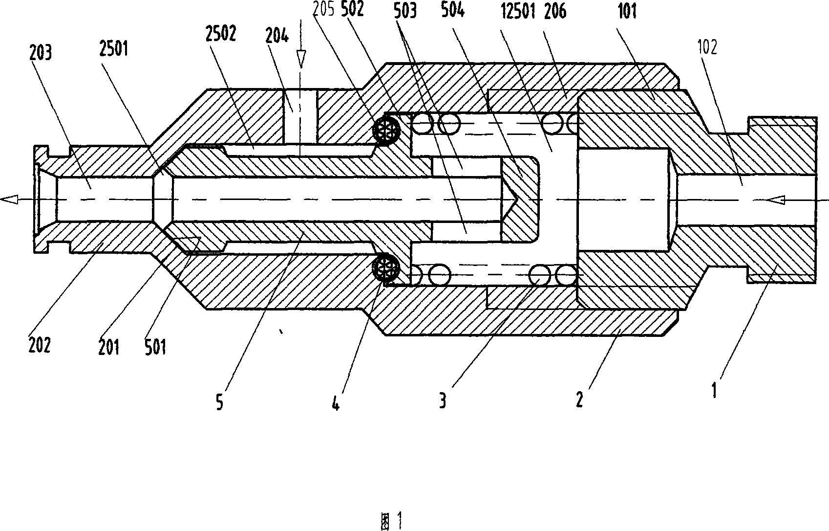
[0027] As shown in Figure 1, the technical solution adopted by the purpose of the present invention is to include the adjustment connecting cap 1 to thread the outer body 2, the built-in injection body 5 in the outer body 2, the inner table surface 205 of the outer body 2 and the convex ring 503 of the injection body 2 There is spacer ring pad 4 between the left side, stage clip 3 is arranged between the right side of projection body 5 protruding ring 503 and the left end face of adjusting connection nut 1 .

[0028] In the present invention, the inner thread 206 of the outer body 2 is engaged with the outer thread 101 of the adjustment connecting cap 1 , and the inner tapered surface 201 of the outer body 2 is in coincident contact with the outer tapered surface 501 of the injection body 5 .

[0029] In the present invention, the adjustment connecting cap 1 has an external thread 101 and a gas fuel injection channel 102 .

[0030] In the present invention, the jetting body 5 ...


PUM


Abstract

This invention relates to a gas-liquid mixed fuel sprayer containing an adjusting connecting cap, an outer body, a jet-injector, an isolation ring pad and a spread spring suitable for hydrogen-mellow mixed combustion internal combustion engines and turbine engines, which is advantaged that low energy combustion and extremely high diffusibility of hydrogen is helpful to complete combustion of liquid fuel, which is good in dispersed pulverization and burnt fully, early burning and deflagration of hydrogen is restrained to a certain stage, so the fuel system and its control method can be simplified greatly.

Description

Technical field [0001] The invention relates to a gas-liquid fuel mixed injector applied to power machinery, in particular to a fuel injection device applied to various internal combustion engines and gas turbine engines for mixed combustion of hydrogen and alcohol, hydrogen and gasoline and diesel. Background technique [0002] The hydrogen engine has the outstanding advantages of high energy conversion efficiency, good power performance and very little pollution. Hydrogen energy will become one of the ideal clean energy sources, and has attracted great attention and widespread use worldwide. In order to solve the problem of hydrogen storage and distribution, or because of the transition from gasoline and diesel to pure hydrogen fuel, or from the consideration of improving the thermal efficiency of the engine, hydrogen-alcohol, hydrogen-gasoline and diesel hybrid vehicles are increasingly becoming the research and development and promotion of countries all over the world. ...

Claims


Application Information

Patent Timeline
IPC IPC(8): F02D19/08F02C7/232
Inventor 李钢坤
Owner 李钢坤
Why Eureka
Try Eureka