Transmitting device for free-space optical transmission

A technology of free space and sending equipment, applied in the direction of free space transmission, transmission system, electromagnetic wave transmission system, etc.

Active Publication Date: 2007-12-26
兹克斯托克资产有限责任公司
View PDF5 Cites 7 Cited by
  • Summary
  • Abstract
  • Description
  • Claims
  • Application Information

AI Technical Summary

Problems solved by technology

[0016] According to the prior art, the problem of the means for delivering said signal to be sent to said lamp has not been dealt with in a manner satisfactory to all applications, since the use of two separate wires is significantly more expensive than just using Conventional wiring of lighting fixtures for lighting

Method used


Image

  • Transmitting device for free-space optical transmission

Examples


Embodiment Construction

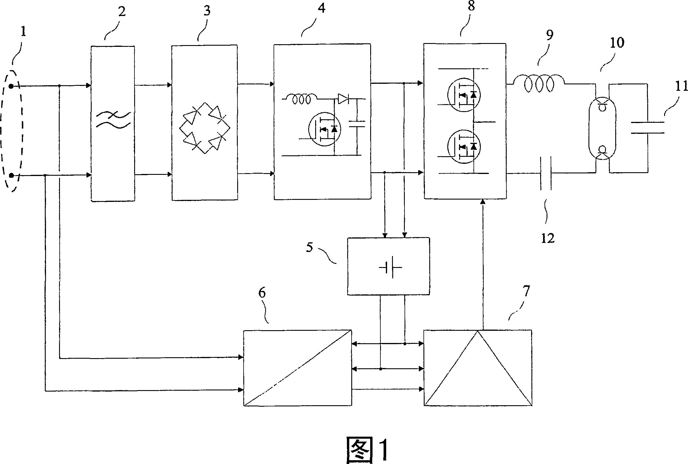
[0034] As an example of a device of the invention given by way of non-limiting example, it is shown in Figure 1 connected to an alternating current energy distribution system through its input terminals (1). The power supply filter (2) can effectively reduce conducted electromagnetic interference generated by the power supply circuit at a frequency higher than 150 kHz according to adjustments related to electromagnetic compatibility. The power supply circuit includes a rectifier (3), a power factor correction circuit (4), a low-voltage power supply (5) and an inverter (8). Said power factor correction circuit (4), well known to experts, is a non-isolated boost converter. It draws a sinusoidal current from the power supply. It therefore provides low emission of harmonic currents according to the regulation concerning electromagnetic compatibility. It also provides pre-adjustment. The inverter (8) comprises a push-pull switching stage, the output of which is connected to a se...


PUM


Abstract

Transmitting device for free-space optical transmission. The invention relates to a transmitting device for transmission through space, using electromagnetic waves of the infrared and / or visible and / or ultraviolet bands produced by one or several discharge lamps. The device is connected by its input terminals (1) to an a.c. energy distribution system. A mains filter (2) reduces the conducted electromagnetic disturbances produced by the power circuits comprising a rectifier (3), a power-factor-correction circuit (4), a low-voltage power supply (5) and an inverter (8). The inverter (8) is connected to a series inductor (9) connected in series with a hot-cathode fluorescent lamp (10) and a capacitor (12), a parallel capacitor (11) allowing an optimal start of the lamp. A receiving set for transmission via power distribution lines (6) delivers ''demodulated signals'' applied to the control circuitry (7) which controls the state of the switches of the inverter (8). The light produced is modulated as a function of the ''demodulated signals''.

Description

technical field [0001] The invention relates to a transmitting device for transmission through space, which uses electromagnetic waves in the infrared and / or visible and / or ultraviolet bands generated by one or more discharge lamps. [0002] French patent application No. 0409939, filed September 20, 2004, entitled "Dispositifd'emission pour la transmission optiqueen espace libre", is hereby incorporated by reference. Background technique [0003] Hereinafter, the word "light" shall stand for electromagnetic radiation, which may comprise visible and / or infrared and / or ultraviolet light. In the following, the word "discharge lamp" shall denote any type of discharge lamp. For example, the lamp may be a low pressure discharge lamp, a mercury vapor fluorescent tube, or a compact fluorescent lamp, or a sodium vapor lamp, etc. This lamp can be, for example, a high-pressure discharge lamp, such as a metal iodide lamp. [0004] The idea of ​​using discharge lamps for optical trans...

Claims


Application Information

Patent Timeline
Patent Type & Authority Applications(China)
IPC IPC(8): H04B10/10H05B41/26H04B10/114H04B10/116
CPCH04B10/1149H04B10/116H04B10/11H05B41/26H04B10/00
Inventor F·布鲁德E·克拉弗利耶
Owner 兹克斯托克资产有限责任公司
Why Eureka
Try Eureka