

Electric welding rod automatic dryer
A technology for welding electrodes and dryers, applied in dryers, drying, progressive dryers, etc., can solve problems such as heat loss, energy waste, inconvenient installation and maintenance, etc., to reduce heat loss and save energy , Easy installation and maintenance
Inactive Publication Date: 2008-01-02
江苏中油船舶电器有限公司
View PDF0 Cites 3 Cited by
- Summary
- Abstract
- Description
- Claims
- Application Information
AI Technical Summary
Problems solved by technology
Most of the existing dryers have the following defects: 1. Because the furnace body is generally a metal frame structure, the heat in the heating chamber is easily lost through the heat conduction of the metal frame, resulting in a waste of energy; The drying process requires that there is a certain difference in the drying temperature between the upper layer and the lower layer of the heating chamber. The existing through-type heating chamber is not easy to control the temperature of the upper and lower layers more accurately; 3. The conveying track in the existing structure Fixed installation on the furnace frame, its installation and maintenance are inconvenient
Method used
View moreImage
Smart ImageViewing Examples

Examples
Embodiment Construction
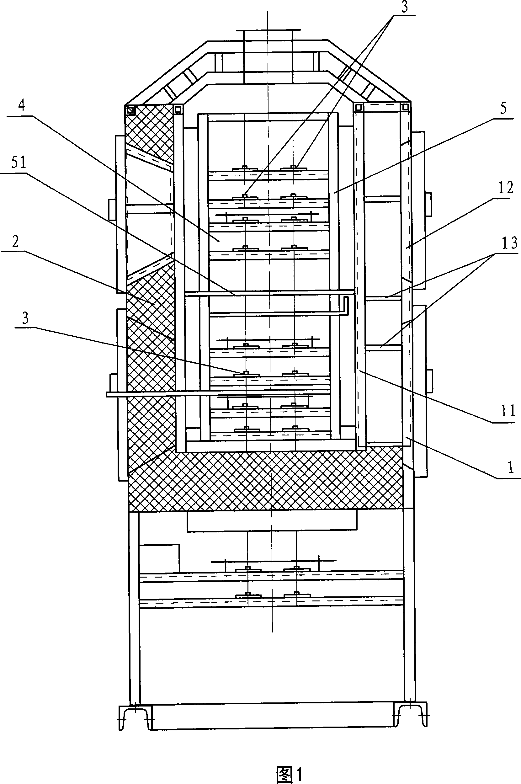
[0009] As shown in the figure, the furnace body of the welding rod drying furnace of the present invention includes a metal frame 1 and a refractory insulation material 2 filled in the metal frame. The metal frame is composed of an inner frame 11 and an outer frame 12, two layers The frames are connected and fixed by connecting bridges 13 arranged at intervals. A movable frame 5 that can be removed from the furnace body is arranged in the heating chamber 4 in the furnace body. A multi-layer conveying track 3 for transporting welding electrodes is installed on the movable frame. The heating chamber is divided into upper and lower parts by a partition 51 .
Login to View More PUM
 Abstract
The invention discloses an automatic dryer of welding rod, which is characterized by the following: comprising a furnace body with metal frame; arranging delivery track in the heating cavity of the furnace body; transferring welding rod with the delivery track; constructing the metal frame with the inner layer frame and the outer layer frame; connecting the inner layer frame and the outer frame through separated metal connecting bridge; filling fire resistive and heat insulating material in the metal frame. This invention possesses small heat loss and convenient assembling.
Description
technical field [0001] The invention relates to a device for producing welding rods, in particular to an automatic drying machine for welding rods. Background technique [0002] The welding rod automatic drying machine is a device used to distribute and dry the welding rod in the automatic production equipment of the welding rod. conveyor track. Most of the existing dryers have the following defects: 1. Because the furnace body is generally a metal frame structure, the heat in the heating chamber is easily lost through the heat conduction of the metal frame, resulting in a waste of energy; The drying process requires a certain difference in the drying temperature between the upper layer and the lower layer of the heating chamber. The existing through-type heating chamber is not easy to control the temperature of the upper and lower layers more accurately; 3. The conveying track in the existing structure It is fixedly installed on the furnace body frame, and its installatio...
Claims
Login to View More Application Information
Patent Timeline
 IPC IPC(8): F26B15/14
Inventor张孝康
Owner江苏中油船舶电器有限公司