
Method for testing motor and testing circuit

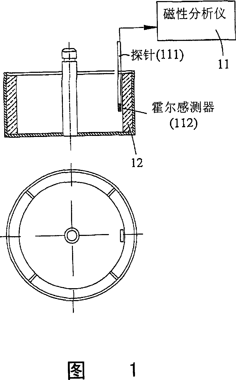
A test method and test circuit technology, applied in the direction of motor generator testing, etc., can solve problems such as time-consuming, unbearable impact on users of measurement results, and inapplicability to production lines.

Inactive Publication Date: 2008-01-02
DELTA ELECTRONICS INC
View PDF0 Cites 27 Cited by
  • Summary
  • Abstract
  • Description
  • Claims
  • Application Information

AI Technical Summary

Problems solved by technology

[0004] (1) It is necessary to adjust the relative position of the permanent magnet and the probe 111 multiple times during the detection process, which consumes a lot of time;
[0005] (2) Probes are relatively fragile and not suitable for production lines;
[0006] (3) The probe has a certain volume, so when it is used to test a micro motor, the influence of the position error caused by the volume of the probe itself on the measurement result will be unbearable to the user; and
[0007] (4) The stator core needs to be removed during the test, so the measurement result is not the air gap magnetic density distribution when the motor is working normally, and it is impossible to conduct a precise analysis of the motor's operating performance based on the result
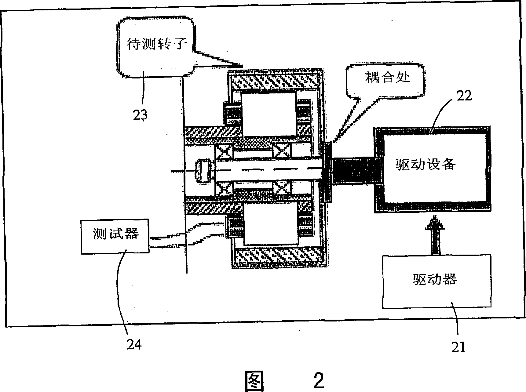
Among them, the existence of the driving device 22 makes the test system very complicated. In addition, it will take a lot of time to complete the alignment of the rotor of the driving device 22 and the rotor of the motor to be tested (the coupling in the figure). Not conducive to production line requirements

Method used


Image

  • Method for testing motor and testing circuit
  • Method for testing motor and testing circuit
  • Method for testing motor and testing circuit

Examples


Embodiment Construction

[0065] Please refer to FIG. 9 , which is a circuit diagram of an embodiment of applying the testing method of the present invention to a single-phase brushless DC motor. The main test circuit is composed of a controller 31 and a signal conditioning circuit 32. In addition, the figure also includes an activation key 37, a relay 36, a power supply Vcc, a motor 35 composed of a drive circuit 33 and a motor winding 34, and other components. (such as resistors R1, R2) and so on.

[0066] In FIG. 9 , the digital controller 31 is used for detection and control, sampling of back EMF and data analysis, etc., and the signal conditioning circuit 32 can perform functions such as zooming in, zooming out, and translation of the back EMF. The digital element controller 31 sends a control signal TK to control whether the wire pack of the relay 36 is energized or not, so as to control the closing and opening of the relay. When the testing method of the present invention is not executed, the a...


PUM


Abstract

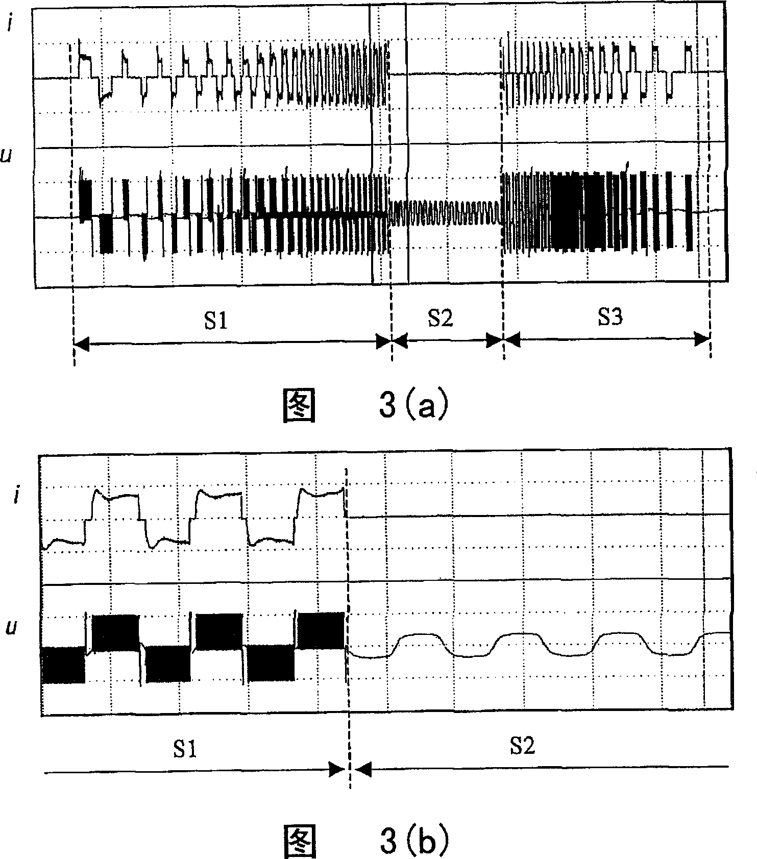
The invention is a testing method and testing circuit of motor, the motor includes a stator and a rotor, the stator possesses a winding, the winding generates a reversing electromotive force when rotor rotates, the testing circuit includes: a controller which is used to receive a activating signal to drive a current to the winding to make rotor rotate, when the rotor achieves definite speed, drive current is stopped to make current degenerated, and when the current in the winding is degenerated to zero, measuring the end voltage of the winding to be a uncompensated reversing electromotive force, and based on voltage of the winding, the value of the rotor can compensate the reversing electromotive force to obtain the reversing electromotive force; and a signal conditioning circuit is coupled to the motor and the controller and condition the voltage signal; thereinto, using the controller to analyze the reversing electromotive force and select at least one character values of the reversing electromotive force, and comparing the at least one character values with the corresponding character value of expected reversing electromotive force to decide whether the charge magnetism of motor is eligible.

Description

【Technical field】 [0001] The present invention refers to a testing method and testing circuit of a motor, especially a testing method and testing circuit of a motor implemented by detecting and analyzing back electromotive force (BEMF). 【Background technique】 [0002] The magnetization quality of the permanent magnet in the permanent magnet motor determines the operating performance characteristics of the motor. Among them, the magnetic analyzer based on the Hall sensor is often used to detect the magnetization quality of the permanent magnet. As shown in Figure 11, it is a schematic diagram of conventionally using a magnetic analyzer to detect a permanent magnet of a motor. In the figure, the permanent magnet is detected by a magnetic analyzer 11 composed of a probe 111 and a Hall sensor 112. The magnetic density distribution on the surface of the permanent magnet can be obtained by the probe 111 rotating once in the rotor 12 . [0003] However, this conventional device ha...

Claims


Application Information

Patent Timeline
IPC IPC(8): G01R31/34
Inventor 吴立建金万兵应建平黄世民黄文喜
Owner DELTA ELECTRONICS INC
Learn More