Plane grid two-dimensional sun-tracing photovoltaic generator

A technology of tracking the sun and photovoltaic power generation, applied in the field of solar photovoltaic power generation, can solve the problems of no economic benefit and high cost, and achieve the effects of saving tracking costs, large carrying capacity and reducing costs

Inactive Publication Date: 2008-01-02
UNIV OF SCI & TECH OF CHINA
View PDF0 Cites 40 Cited by
  • Summary
  • Abstract
  • Description
  • Claims
  • Application Information

AI Technical Summary

Problems solved by technology

The cost of the tracking device currently used is very expensive. The cost of the traditional one-dimensional tracking ...

Method used


Image

  • Plane grid two-dimensional sun-tracing photovoltaic generator
  • Plane grid two-dimensional sun-tracing photovoltaic generator
  • Plane grid two-dimensional sun-tracing photovoltaic generator

Examples


Embodiment 1

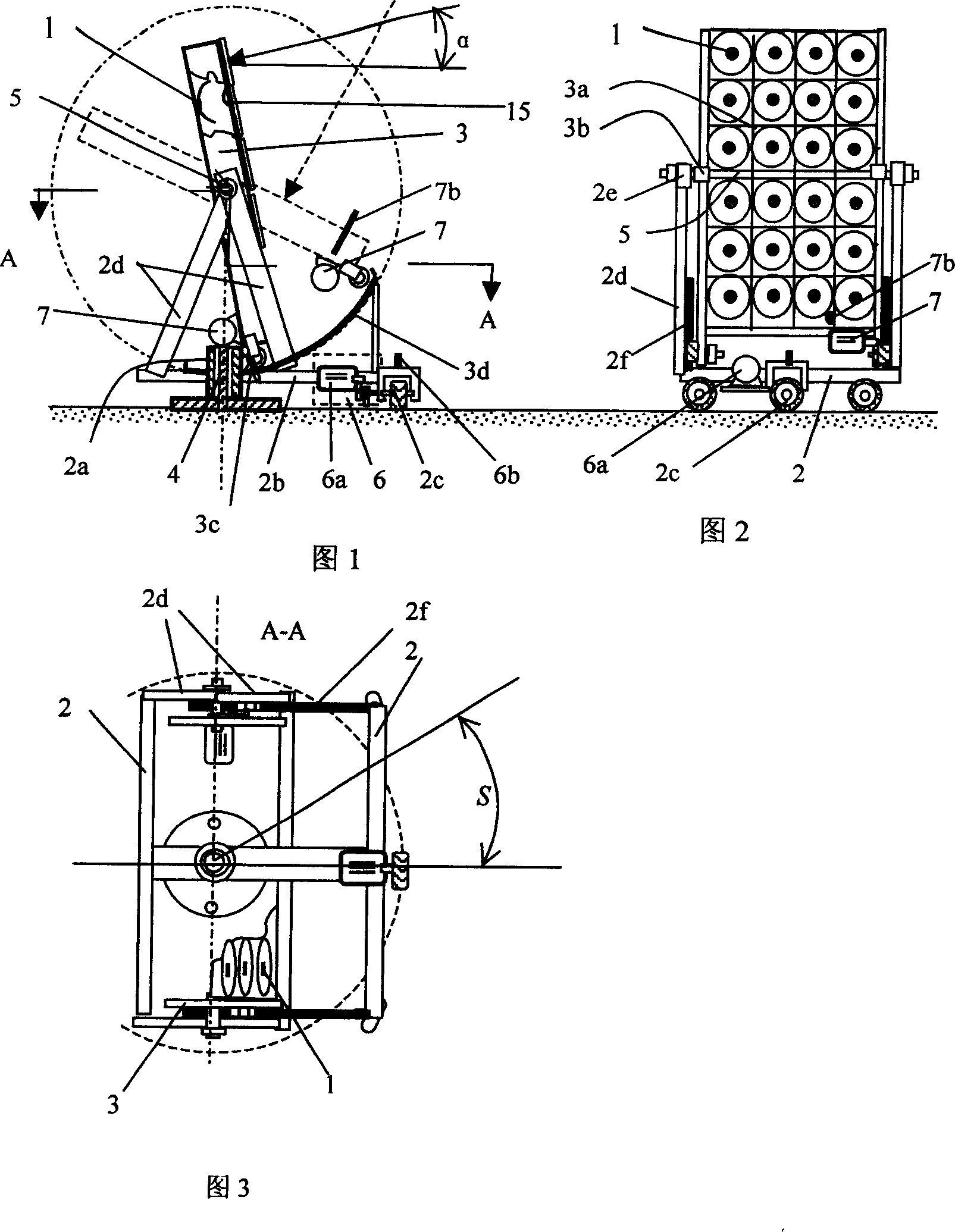
[0029] The structural relationship and working principle of Embodiment 1 are jointly illustrated by FIGS. 1 , 2 and 3 .

[0030] The device of Example 1 mainly includes a solar photovoltaic generator 1 and a two-dimensional tracking mechanism. Wherein the simplest solar photovoltaic generator is a flat solar panel; the two-dimensional tracking mechanism consists of a horizontal plane rotating support 2, an inclined plane shaking support 3, a vertical fixed axis 4, a horizontal axis 5, a sun azimuth tracking driver 6 and The sun altitude angle tracking driver 7 is composed of; the vertical fixed axis 4 is the basis of the whole device, and the horizontal plane rotating bracket 2 is driven by the sun azimuth angle tracking driver 6 to rotate around the vertical fixed axis 4; the inclined plane rocking bracket 3 and the horizontal axis 5 are mounted on the horizontal plane On the rotating bracket 2, the solar photovoltaic generator 1 is installed on the tilting surface rocking br...

Embodiment 2

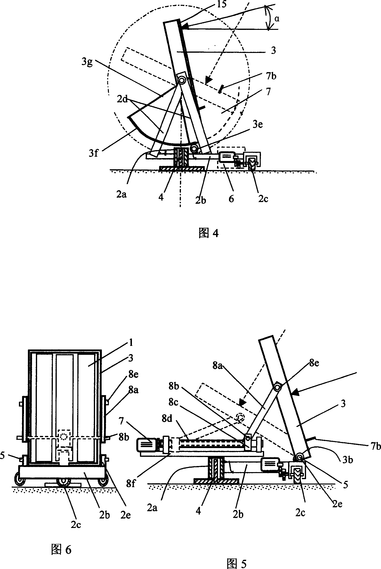
[0032] The structural relationship of Embodiment 2 is illustrated by FIG. 4 .

[0033] The device of embodiment 2 has only a small part of difference with the device of embodiment 1, that is, the rocking mechanism of the inclined surface rocking support 3 is different, and the rest are the same. As shown in the figure, the toothed rocking roller 3e mounted on the plane support 2b drives the toothed circular arc track 3f engaged with it to rotate on the lower end of the frame of the rocking support 3. The center of the toothed circular arc track 3f is the horizontal axis 5 axis, the radius of curvature is the radial distance from the axis of the horizontal shaft 5 to the upper edge of the toothed rocking roller 3e wheel periphery, which is connected to the axle sleeve 3b of the rocking bracket 3 by the spoke 3g, and the toothed rocking roller 3e is formed by the height of the sun The angle tracking driver 7 drives the rotation and controls the rotational speed. At this time, t...

Embodiment 3

[0034] The structural relationship of Embodiment 3 is illustrated by Fig. 5 and Fig. 6 .

[0035] The difference between the device of embodiment 3 and the devices of embodiments 1 and 2 is that the device drives the rocking mechanism of the inclined surface rocking support 3 to change the inclination angle, and the shaft sleeve 3b of the inclined surface shaking support 3 moves to the lower end of the frame, horizontal The shaft 5 also moves down to the bearing seat 2e installed on the horizontal plane rotating support 2, the bearing seat 2e is located at the far end of the plane support 2b away from the vertical fixed shaft 4; The rotation pair 8e is connected to one end of a pair of rocking bars 8a respectively, and the other end of the rocking rod 8a is connected to a horizontal shaft 8b through the lower rotating shaft, and the horizontal shaft is connected with a slide block 8c, and the slide block moves on a linear track. The slide block is a nut, and the linear track i...


PUM

PropertyMeasurementUnit
Wavelengthaaaaaaaaaa

Abstract

The invention provides a photovoltaic generator of plane network support two-dimension sun track, belonging to the technical field of solar-energy photovoltaic generation. The invention comprises a solar-energy photovoltaic generator and a sun tracker, wherein the sun tracker is a two-dimension track device, which comprises a horizontal rotary support, an inclined swing support, a vertical fixed shaft, a horizontal shaft, a sun direction track driver, and a sun altitude angle track driver. The solar-energy photovoltaic generator can be provided with a condenser and a self heat radiation in disc or groove shape while a plurality of photovoltaic generators are mounted on a plane network support of the inclined swing support. The horizontal rotary support rotates around the vertical fixed shaft. The inclined swing support rotates around the horizontal shaft. Therefore, the normal line of the photoelectric battery plate of the solar-energy photovoltaic generator is toward sun all the time. The invention has stable structure, small drive force, multiple load of elements, saved track cost, improved condense ratio caused by the utilization of condenser and self heat radiator, and improved generating efficiency.

Description

Technical field: [0001] The invention relates to the field of solar photovoltaic power generation, in particular to a solar photovoltaic generator tracking mechanism for the sun. Background technique: [0002] At present, the photovoltaic power generation method of solar energy generally allows sunlight to be projected on a flat-plate solar panel with a fixed inclination angle. The photovoltaic cells used are mainly monocrystalline silicon and polycrystalline silicon semiconductor materials, and the power generation efficiency is about 14% of the projected solar radiation power. ~16%. Photovoltaic cells with multilayer P-N junctions can be used for focused photovoltaic power generation, but they are too expensive, so they are only used in small quantities. The biggest problem with solar photovoltaic power generation is that the investment in power generation equipment is too high and the cost of power generation is too expensive. The main reason is: the cost of photovoltai...

Claims


Application Information

Patent Timeline
IPC IPC(8): H02N6/00G05D3/00G05D3/12H02S20/32
CPCF24J2002/5479F24J2/542Y02E10/47F24S30/452F24S2030/145Y02E10/50
Inventor 陈则韶
Owner UNIV OF SCI & TECH OF CHINA
Why Eureka
Try Eureka