Method for manufacturing plate type heat pipe with ultrasonic welding

An ultrasonic welding and flat heat pipe technology, applied in application, manufacturing tools, welding equipment, etc., can solve the problems affecting the heat dissipation effect of the flat heat pipe, the flatness of the pressure jig, and the heat conduction of the metal copper mesh. The effect of improving the manufacturing method, saving the process time, and improving the heat dissipation performance

Active Publication Date: 2008-01-09
ASIA VITAL COMPONENTS SHENZHEN CO LTD
View PDF0 Cites 9 Cited by
  • Summary
  • Abstract
  • Description
  • Claims
  • Application Information

AI Technical Summary

Problems solved by technology

In the production process of this kind of flat heat pipe, whether the connection between the finer mesh and the thicker mesh metal copper mesh is accurate will affect the heat conduction between the metal copper mesh, and then affect the heat dissipation effect of the flat heat pipe
[0011] In addition, the use of general diffusion bonding is also easily affected by the flatness of the pressure-applying jig.
If the flatness of the jig is not good, it is easy to cause poor lamination between the components at the press joint of the jig, resulting in insufficient strength and tightness after diffusion bond

Method used


Image

  • Method for manufacturing plate type heat pipe with ultrasonic welding
  • Method for manufacturing plate type heat pipe with ultrasonic welding
  • Method for manufacturing plate type heat pipe with ultrasonic welding

Examples


Embodiment Construction

[0059] In order to further explain the technical means and effects that the present invention takes to achieve the intended purpose of the invention, below in conjunction with the accompanying drawings and preferred embodiments, the specific implementation methods, The manufacturing method, steps, features and effects thereof are described in detail below.

[0060] The method for manufacturing flat heat pipes using ultrasonic welding in a preferred embodiment of the present invention comprises the following steps:

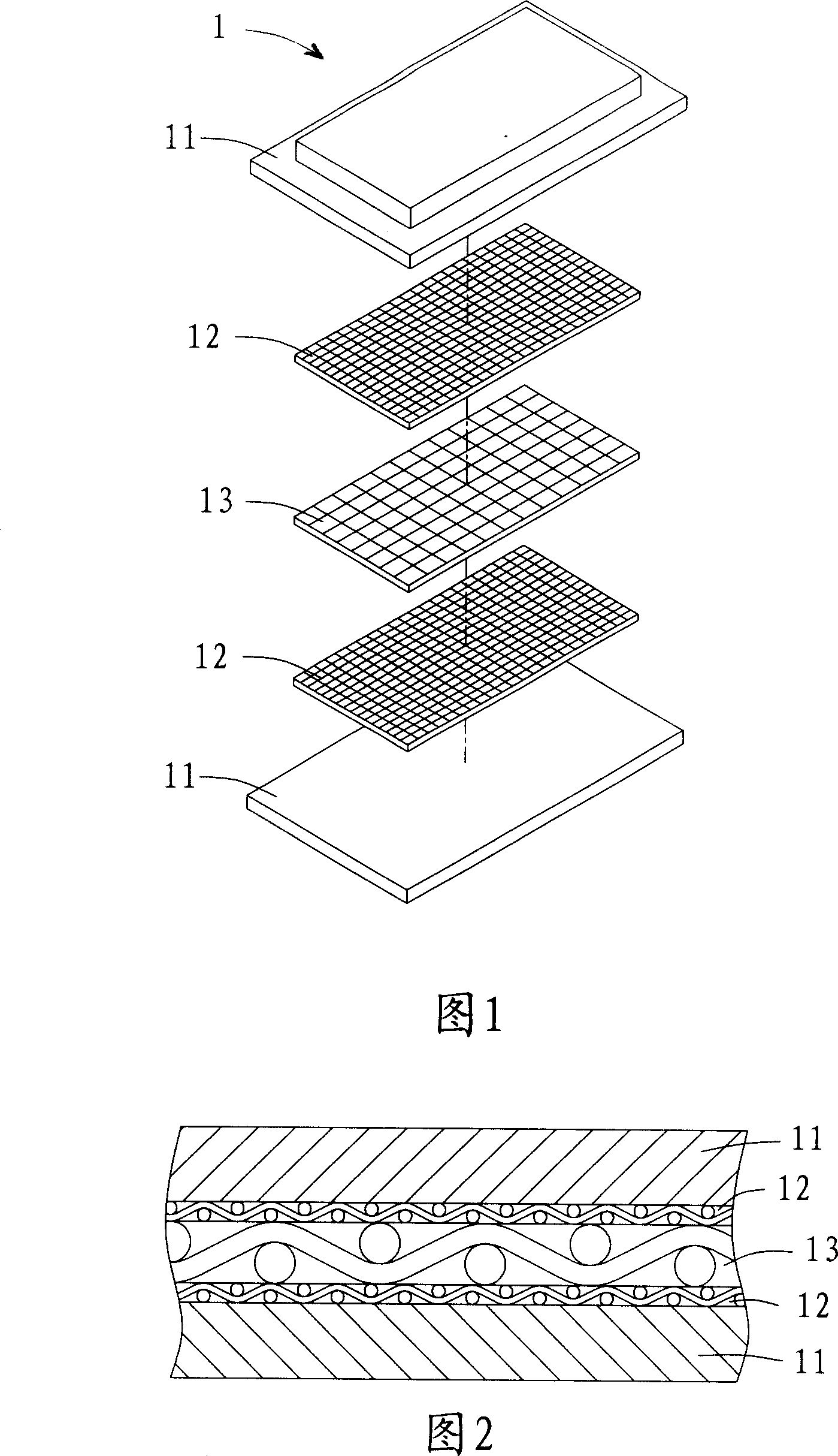
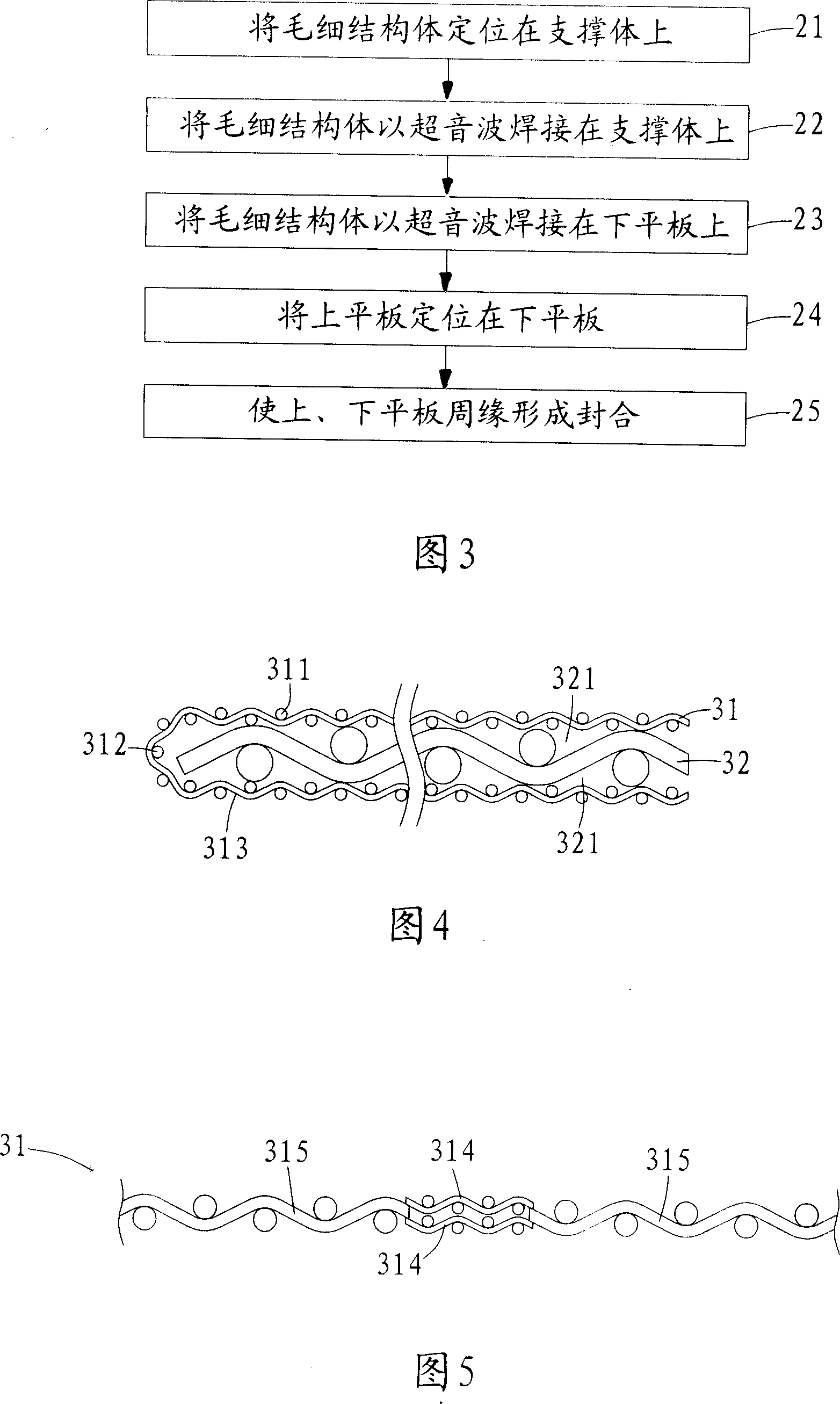
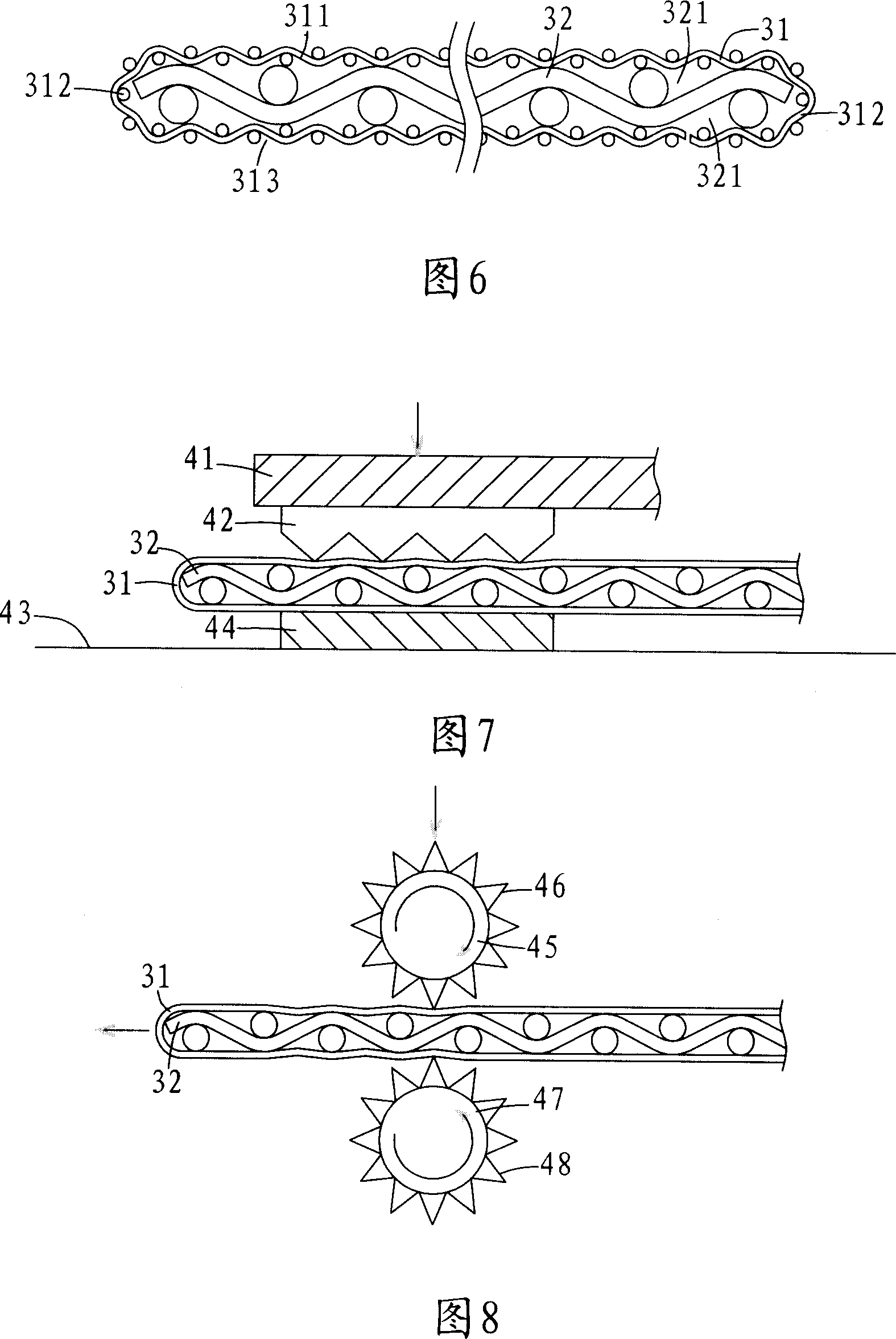
[0061] First, please refer to FIG. 3 , which is a flow chart of a preferred embodiment of the manufacturing method of the flat-plate heat pipe using ultrasonic welding in the present invention. In step 21 , the capillary structure 31 is positioned on the support 32 . The positioning methods can be shown in Figure 4 and Figure 6 respectively.

[0062] First please refer to Fig. 4, which is a partial side view sectional view of the preferred embodiment of the prese...


PUM


Abstract

The ultrasonic welding process for making plate heat pipe includes the following steps: 1. ultrasonically welding capillary structure to one of the upper plate and the lower plate and superposing these two plates with the capillary structure in between; and 2. sealing the plates with the capillary structure inside. The ultrasonically welded plate heat pipe has high bond strength, high tightness, lowered heat resistance and high heat dissipating effect, and shortened production process.

Description

technical field [0001] The invention relates to a method for manufacturing a flat heat pipe, in particular to a method for manufacturing a flat heat pipe using ultrasonic welding. Background technique [0002] Since the integration density of integrated circuit components such as a central processing unit (CPU) continues to increase, the heat generation density thereof also continues to increase. If the heat cannot be effectively dissipated, the working performance of the components will be affected. [0003] Under the trend that portable electronic devices are becoming thinner, thinner and smaller, the problem of heat dissipation is becoming more and more serious, and general heat dissipation devices are gradually facing the bottleneck that it is difficult to improve the heat dissipation effect. [0004] Therefore, the emergence of flat heat pipes can be used as a good heat dissipation device for portable electronic devices in due course. [0005] The operating principle o...

Claims


Application Information

Patent Timeline
IPC IPC(8): B23K20/10B23K20/26B23P15/26B23K101/14
Inventor 杨修维陈佩佩余文华郑兆翔
Owner ASIA VITAL COMPONENTS SHENZHEN CO LTD
Why Eureka
Try Eureka