Monostable self-locking type air gas variable permanent magnet operation device

A permanent magnet operation, self-locking technology, applied in electrical components, high-voltage air circuit breakers, power devices inside switches, etc. The problem of increasing the stroke of the moving iron core of the magnetic mechanism can reduce the contact collision and bounce, reduce the excitation current, and increase the starting ability.

Inactive Publication Date: 2008-01-16
BEIJING JIAOTONG UNIV
View PDF0 Cites 22 Cited by
  • Summary
  • Abstract
  • Description
  • Claims
  • Application Information

AI Technical Summary

Problems solved by technology

As the application voltage increases, the opening distance of the circuit breaker contacts increases, and the stroke of the moving iron core of the permanent magnet mechanism increases, resulting in an increase in the closing starting current of the mechanism.
The increase of excitation current causes control difficulties, increased energy consumption, serious heat generation, and intensified collision between the moving iron core and the static iron core. Field application implementation
There are many types of permanent magnet mechanisms with different structures. Most of them are used in the medium voltage field of 10KV-24KV. So far, only a few can be used at the voltage level of 40.5KV. The application of permanent magnet mechanisms at the level of 72.5KV is only in the experimental stage, however, the mechanisms themselves are simply structural improvements without fundamental changes
For today's high-voltage field of more than 100KV, there are almost no research reports on the application of permanent magnet mechanisms

Method used


Image

  • Monostable self-locking type air gas variable permanent magnet operation device
  • Monostable self-locking type air gas variable permanent magnet operation device
  • Monostable self-locking type air gas variable permanent magnet operation device

Examples


Embodiment Construction

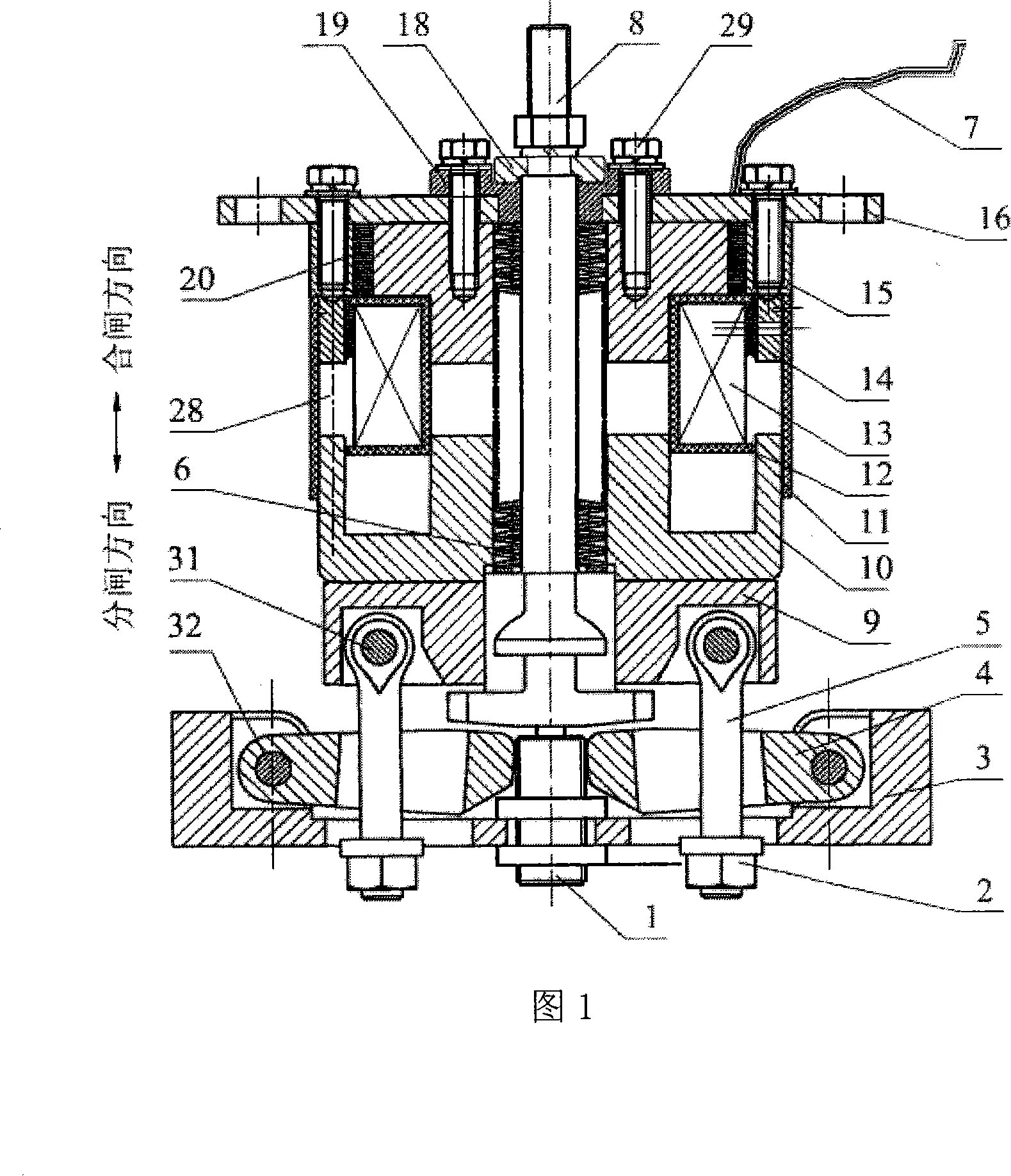
[0025] The invention provides a monostable self-locking variable air gap permanent magnet operating mechanism suitable for large opening distance and high voltage circuit breaker, which is mainly composed of four major systems: magnetic circuit system, transmission system, locking system and support system. .

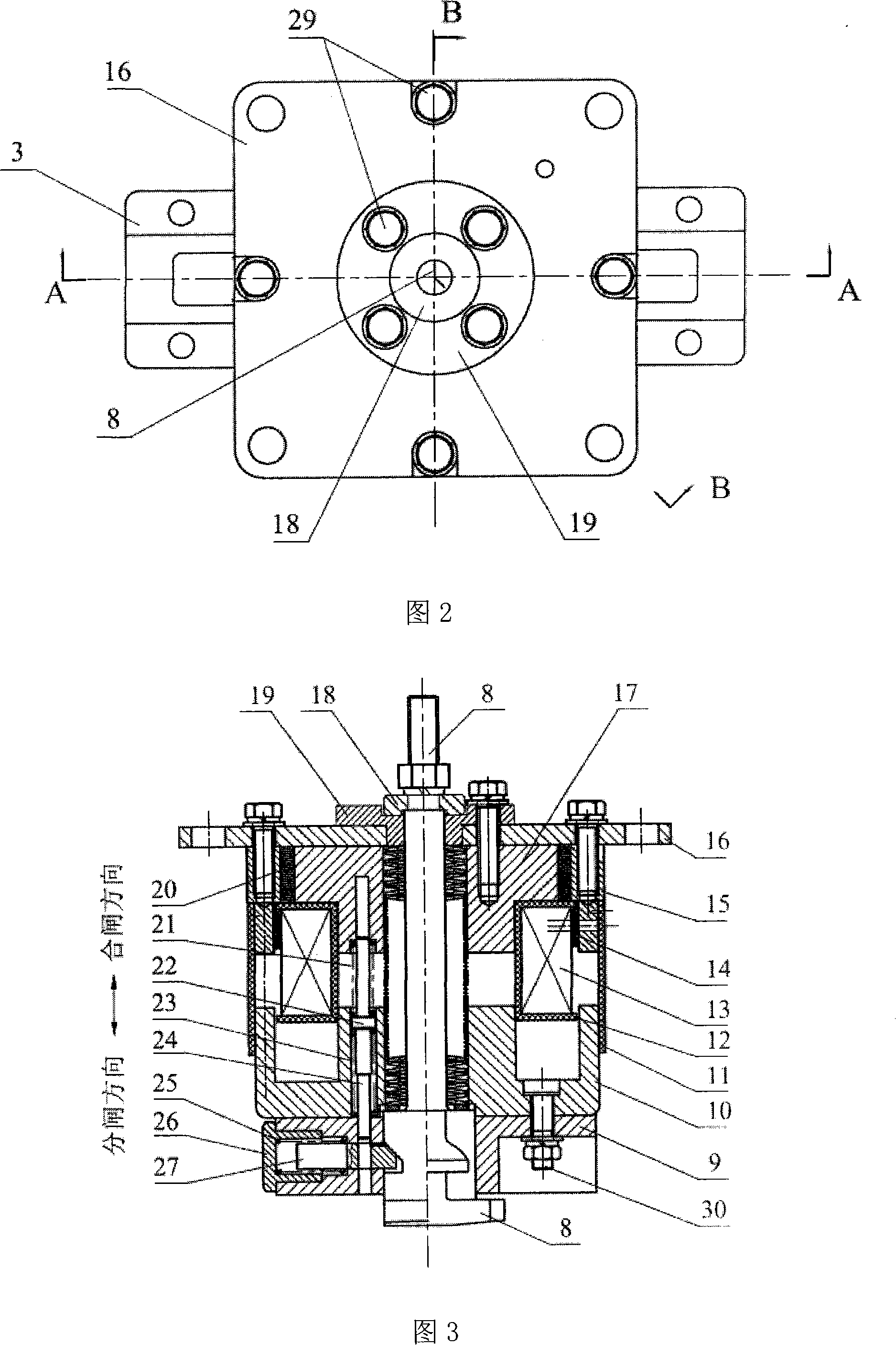
[0026] In the monostable self-locking variable air gap permanent magnet operating mechanism shown in Fig. 1, Fig. 2 and Fig. 3, the magnetic circuit system is axisymmetric, mainly composed of a moving iron core 10, an outer static iron core 15, an inner static Iron core 17 and permanent magnet 20 form. The permanent magnet 20 is embedded between the inner static iron core 17 and the outer static iron core 15; the electromagnetic coil 13 is embedded in the coil groove formed between the inner static iron core 17, the outer static iron core 15 and the moving iron core 10, And be fixed by epoxy resin ring 14 and inner static iron core 17, outer static iron core 15, guard ...


PUM


Abstract

The invention discloses a mono-stability self-locking gas clearance permanent operating mechanism used for large open contact and high voltage breaker in the medium and high voltage electrical switch field. When used for medium voltage breakers, the mechanism can lower exciting current and increase electromagnetic force. The permanent magnetic operation mechanism mainly consists of a magnetic circuit system, a transmission system, a locking system, and a supporting system. Permanent magnet of the magnetic circuit system is embedded between the internal and external static iron cores; magnetic coils are embedded in the coil groove constituted by the internal and external static iron cores and dynamic iron cores. Clearance is reserved between the internal, external static iron cores and dynamic iron core. Core shaft is pressed on a limiting block by a nut after pulling through a lock disc, a dynamic iron core, and a switch spring, an end cover, and a limiting block in the magnetic circuit system. The invention can well control the closing and opening speed of switch contacts and reduce the collision and bouncing of contacts. Suitable for breakers of different voltage grades, particularly high voltage vacuum breakers with big open contacts, the invention can lower exciting current and energy consumption more reliably.

Description

technical field [0001] The invention belongs to the field of medium and high voltage electrical switches. It particularly relates to a monostable self-locking variable air gap permanent magnet operating mechanism used in conjunction with a vacuum circuit breaker. Background technique [0002] Due to the advantages of high reliability, maintenance-free and good output characteristics, the permanent magnet mechanism is used in conjunction with vacuum circuit breakers and is more and more widely used in the field of medium and high voltage switches. As the application voltage increases, the opening distance of the circuit breaker contacts increases, and the stroke of the moving iron core of the permanent magnet mechanism increases, resulting in an increase in the closing starting current of the mechanism. The increase of excitation current causes control difficulties, increased energy consumption, serious heat generation, and intensified collision between the moving iron core ...

Claims


Application Information

Patent Timeline
Patent Type & Authority Applications(China)
IPC IPC(8): H01H3/28H01H33/38H01H33/666
Inventor 朱学贵王毅
Owner BEIJING JIAOTONG UNIV
Why Eureka
Try Eureka