Cool electronic ultraviolet lamp

An ultraviolet lamp and electronic technology, applied in lamp parts, fluorescent screen lamps, etc., can solve problems such as environmental pollution

Inactive Publication Date: 2011-06-08
ENERGY RESOURCES INT
View PDF0 Cites 0 Cited by
  • Summary
  • Abstract
  • Description
  • Claims
  • Application Information

AI Technical Summary

Problems solved by technology

[0004] Therefore, the industry will regularly produce a large number of discarded high-concentration mercury lamps for replacement. Since the recycling technology is not yet mature, it has not yet been announced as waste that should be recycled, and this will become a hidden concern for environmental pollution.

Method used


Image

  • Cool electronic ultraviolet lamp
  • Cool electronic ultraviolet lamp
  • Cool electronic ultraviolet lamp

Examples


Embodiment Construction

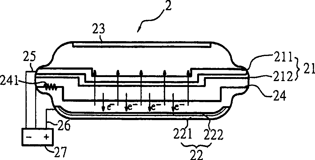
[0048] In order to solve environmental pollution, but can continue to use ultraviolet lamps to carry out required work, the present invention provides an ultraviolet lamp, which uses a carbon film deposited on a nickel substrate as a cathode to emit electrons, which hit the fluorescent material coated on the anode to emit Ultraviolet light, and then choose to coat a photocatalyst (titanium dioxide) on the light-emitting side of the lamp tube, and use ultraviolet light to trigger titanium dioxide to generate hydroxyl radicals for sterilization.

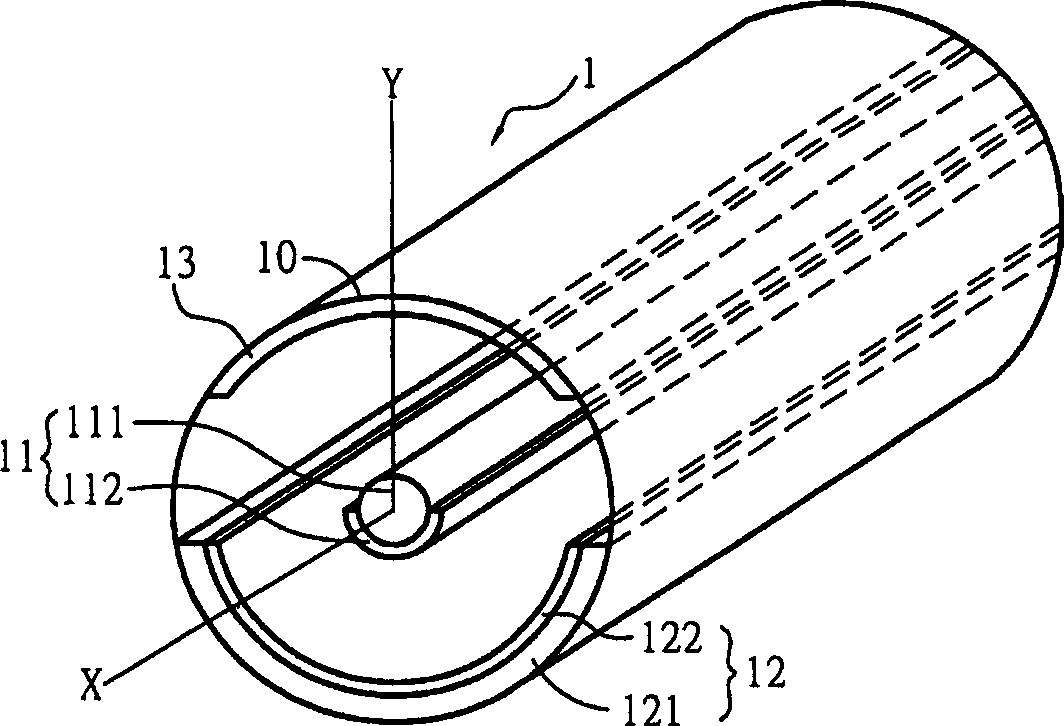
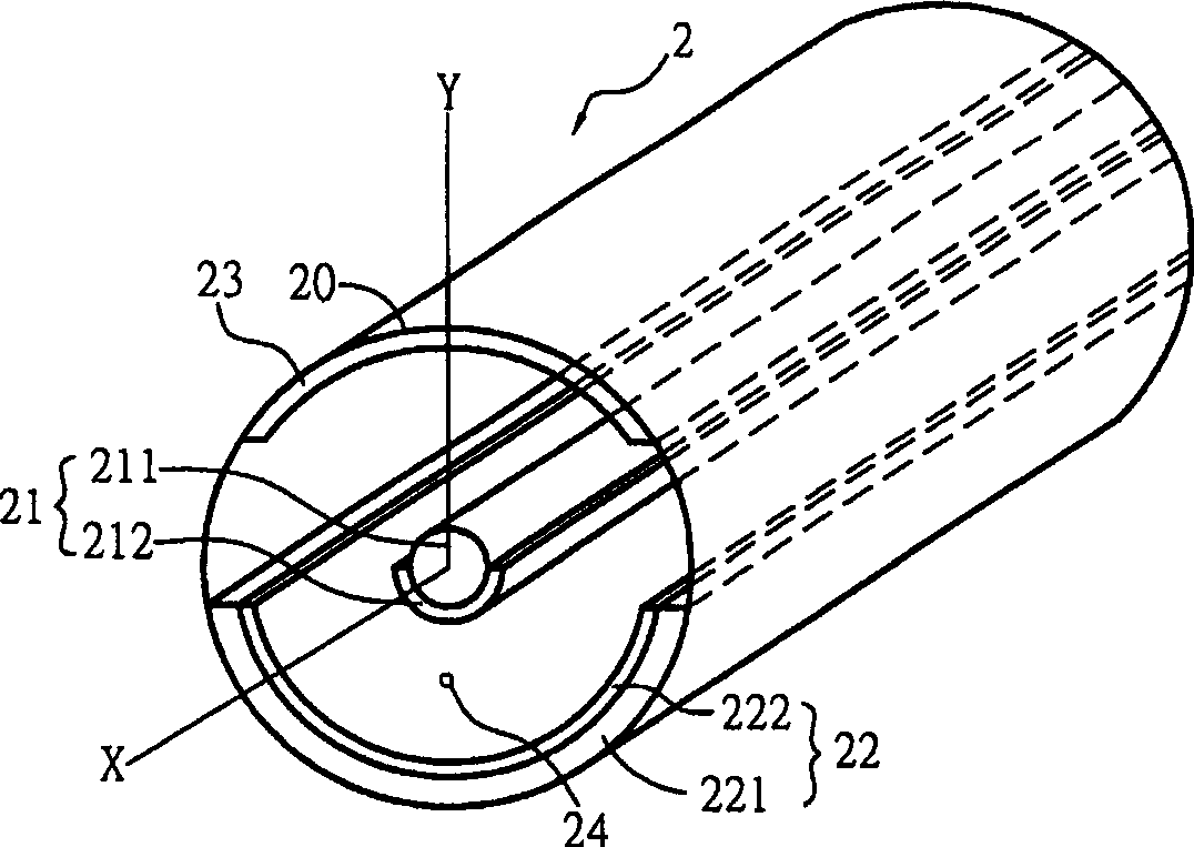
[0049] Please refer to Figure 1A and Figure 1B Shown are the ultraviolet lamps of the first and second embodiments of the present invention. Figure 1A The shown ultraviolet lamp 1 includes a cylindrical quartz lamp tube 10, a reflective metal layer 121 (conductive layer) is formed on the surface of the inner portion of the quartz lamp tube, and a fluorescent coating 122 is formed on the metal layer 121. Above, the reflective metal l...


PUM


Abstract

A cold electron infrared ray lamp includes: a quartz lamp tube, a cathode composed of carbon film layer at the bottom of nickel base, and an anode composed of a conductive layer and a fluorescent coating smeared on the conductive layer. The light wave length scope of the fluorescent coating is 280 to 400nm. The invention also discloses another old electron infrared ray lamp, which, on the basis of the previous old electron infrared ray lamp, is provided with a metal grid between the cathode and anode. Another old electron infrared ray lamp includes: a plane cathode composed of carbon film layer on the surface of the nickel metal plate; and a plane anode composed of a transparent conductive layer on a glass base plate and a fluorescent coating smeared on the transparent conductive layer. The light wave length scope of the fluorescent coating is 280 to 400nm. A metal grid is arranged between the cathode and anode to lower the driving voltage of the ultraviolet radiation lamp; and a quartz lamp tube fixes the cathode and anode in the metal grid. As a green lighting appliance, the invention can protect environment and reduce pollution.

Description

technical field [0001] The present invention relates to an ultraviolet lamp, in particular to a lamp that uses a carbon film as an electron field emitter to emit electrons and strike a fluorescent coating to generate ultraviolet light. Background technique [0002] With the economic prosperity brought about by global industrialization, human life has obviously improved a lot compared with the previous century. However, while enjoying the convenience brought by industrialization, some people who are sensitive to environmental changes began to worry about the environmental damage caused by industrialization, and combined government agencies and engineering R&D personnel to seek solutions to prevent environmental degradation. Even worse. [0003] As far as current lighting sources are concerned, most lighting equipment contains mercury, because mercury vapor must be used as the discharge medium in the lighting process, and there is currently no suitable substitute available; a...

Claims


Application Information

Patent Timeline
Patent Type & Authority Patents(China)
IPC IPC(8): H01J63/02H01J63/06
Inventor 贾淑瑜
Owner ENERGY RESOURCES INT
Why Eureka
Try Eureka