Hybrid vehicle

A technology for hybrid vehicles and vehicles, which is applied in the direction of hybrid vehicles, motor vehicles, electric vehicles, etc., and can solve problems such as large changes in engine speed, large residual driving force, and inability to cope

Active Publication Date: 2008-01-23
HONDA MOTOR CO LTD
View PDF0 Cites 10 Cited by
  • Summary
  • Abstract
  • Description
  • Claims
  • Application Information

AI Technical Summary

Problems solved by technology

[0005] However, in the series mode, there may be a problem that the fuel consumption rate of the vehicle decreases due to the decrease in the transmission efficiency of the driving force
In addition, when driving only by the engine through the first transmission path of the gear ratio transmission device including a low coefficient ratio, the vehicle travels with a low coefficient gear ratio set to realize the engine driving force characteristic capable of reaching the maximum speed Vmax, and corresponds to normal driving. When the vehicle speed changes greatly, the engine speed changes greatly, and the engine speed area with high fuel consumption rate cannot be selected for normal driving, so the fuel consumption rate drops.
[0006] In particular, in the combination of engine drive and motor drive in a hybrid vehicle equipped with a large displacement engine, since it is a large displacement engine, the residual driving force is large, and there may be a possibility of including the above-mentioned low coefficient The problem that the fuel consumption rate in the first transmission path of the gear ratio is significantly reduced in the setting of the gear ratio
In addition, even in the case of combining with such a large-displacement engine, the combination of output characteristic variable mechanisms such as deactivation of cylinders on a large-displacement multi-cylinder engine to achieve an increase in fuel consumption cannot give full play. The advantages of the variable mechanism of the variable output characteristics of the cylinder in order to improve the fuel consumption under the setting of the low coefficient gear ratio as mentioned above
[0007] In addition, in Patent Document 1, there is no mention of the selection method of the driving state controlled by the driver, such as the shift lever, so it cannot cope with the situation that does not follow the driver's intention.

Method used


Image

  • Hybrid vehicle
  • Hybrid vehicle
  • Hybrid vehicle

Examples


no. 1 example

[0018] Next, a hybrid vehicle according to a first embodiment of the present invention will be described with reference to FIGS. 1 , 2 and 5 .

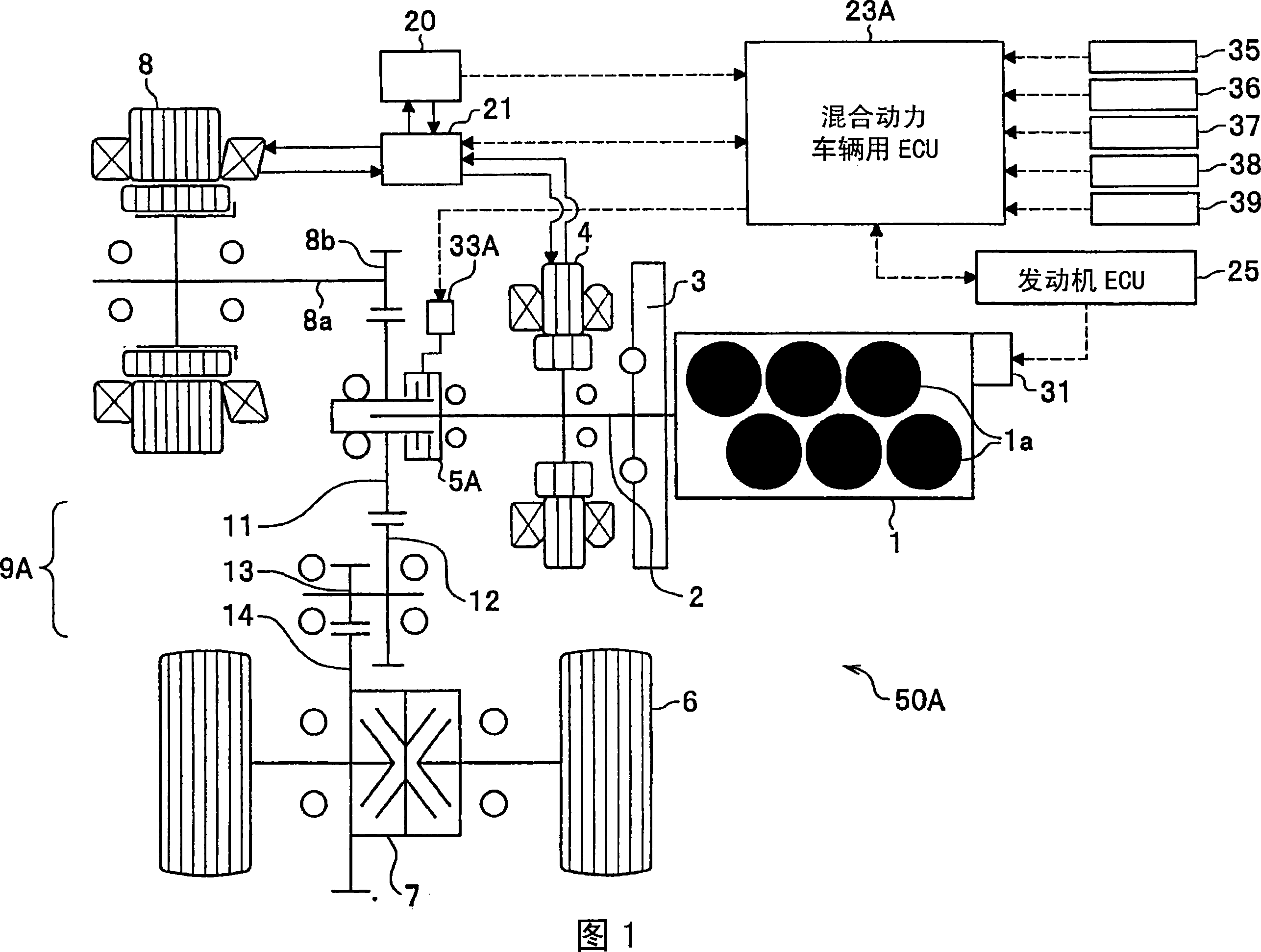
[0019] FIG. 1 is a schematic diagram of an entire hybrid vehicle according to an embodiment of the present invention, showing a transmission path of a driving force of an electric motor and an engine whose speed is changed by a fixed gear.

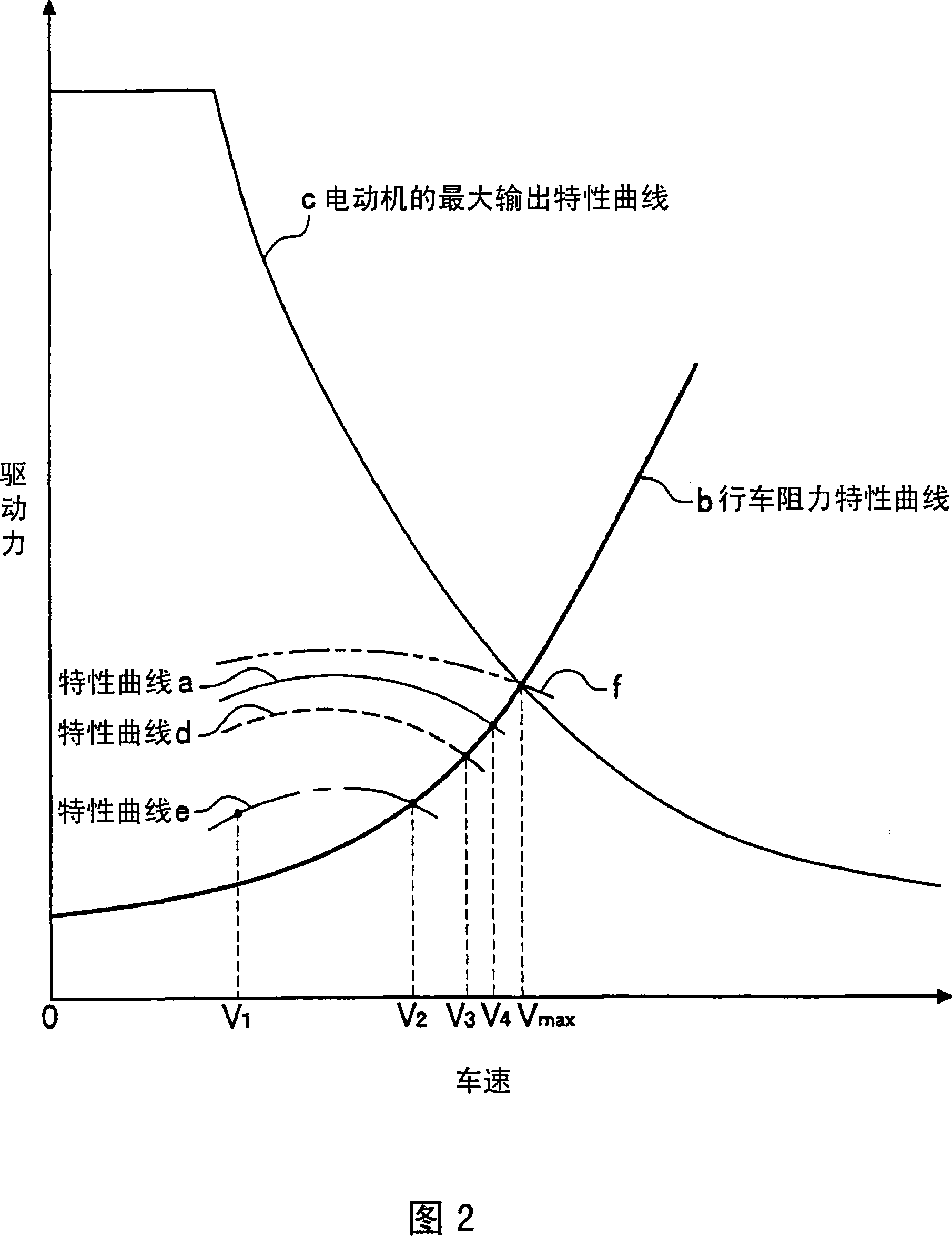
[0020] FIG. 2 is a characteristic diagram of the driving force of the hybrid vehicle of the present embodiment. In FIG. 2 , the horizontal axis represents vehicle speed, and the vertical axis represents driving force or running resistance.

[0021] FIG. 5 is a schematic diagram illustrating the control of the disconnecting device of the hybrid vehicle of the present invention.

[0022] A hybrid vehicle 50A according to an embodiment of the present invention is configured to include a first transmission path for transmitting the driving force of the engine 1 to the drive wheels 6 to drive the vehi...

no. 2 example

[0066] Next, a hybrid vehicle according to a second embodiment of the present invention will be described with reference to FIGS. 3 and 4 (see FIG. 2 as appropriate).

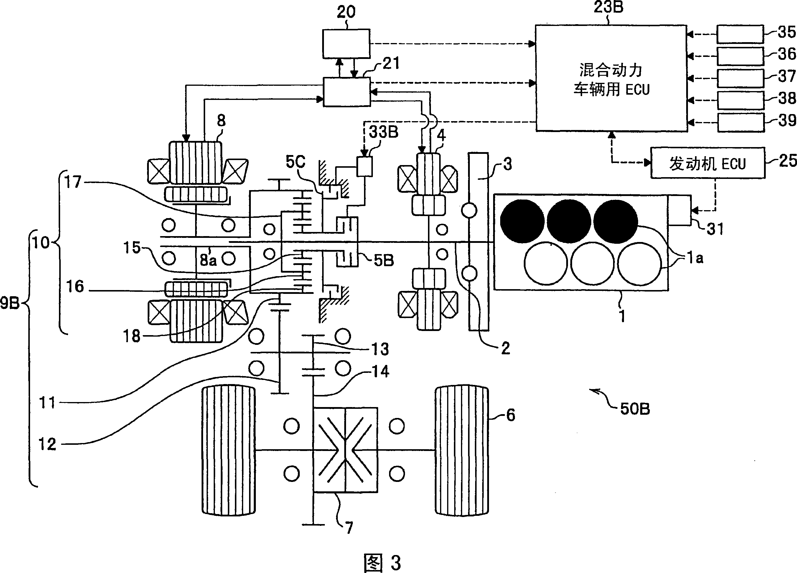
[0067] 3 is a schematic diagram of an entire hybrid vehicle according to an embodiment of the present invention, showing a transmission path of driving force of an electric motor and an engine.

[0068] The hybrid vehicle 50B of the present embodiment includes: a first transmission path for transmitting the driving force of the engine 1 to the drive wheels 6 to drive the vehicle; and a second transmission path for transmitting the driving force of the electric motor 8 to the drive wheels 6 to drive the vehicle. , select one or both of these first transmission route and second transmission route, and travel. In the hybrid vehicle 50B of the second embodiment, the difference from the hybrid vehicle 50A of the first embodiment is that instead of the direct connection clutch 5A of the first embodiment, a switchable...


PUM


Abstract

PROBLEM TO BE SOLVED: To provide a hybrid vehicle which can raise fuel consumption efficiency of a vehicle further at steady traveling time.SOLUTION: In a driving force property of a hybrid vehicle, a speed reduction ratio by engine driving is assumed to be fixed. The speed reduction ratio is set so that it can accelerate only up to the highest vehicle speed V<SB>4< / SB>at maximum output time of the engine at steady traveling time, and cannot accelerate to the highest speed V<SB>max< / SB>of the hybrid vehicle. At steady traveling time where the vehicle speed is V<SB>1< / SB>to V<SB>4< / SB>, it travels with engine driving force in principle. From vehicle speed V<SB>4< / SB>to the maximum speed V<SB>max< / SB>, desired vehicle speed is realized by motor driving. Fuel consumption efficiency can be raised since engine load at steady traveling time is reduced by setting of such a speed reduction ratio and utilization of travel modes. When low output is achieved by an engine output characteristics change mechanism, for example, at cylinder asleep operation of the engine, output becomes as shown by a characteristic curve d which indicates the engine driving force property and the fuel consumption efficiency can be raised further.

Description

technical field [0001] The present invention relates to a hybrid vehicle which travels by combining the engine driving force of an engine (internal combustion engine) and the electric motor driving force of an electric motor (motor), and more particularly relates to a hybrid vehicle which has a device for transmitting the engine driving force to drive wheels The first transmission path and the second transmission path that transmits the driving force of the motor to the drive wheels. Background technique [0002] At present, a well-known hybrid vehicle uses the respective driving force characteristics of the engine and the electric motor to travel through the second transmission path that transmits the driving force of the electric motor to the driving wheels within a vehicle speed range below a certain speed (vehicle speed V1). In the vehicle speed range above the vehicle speed V1, use the second transmission path and the first transmission path that transmits the driving f...

Claims


Application Information

Patent Timeline
IPC IPC(8): B60K6/54B60L50/15B60L50/16
CPCY02T10/6286Y02T10/6239Y02T10/6234Y02T10/7077Y02T10/62Y02T10/7072
Inventor 森下尚久汤本俊行岩田和之本多健司浦野纯司
Owner HONDA MOTOR CO LTD
Why Eureka
Try Eureka