Heating high temperature valve and uses thereof

A valve and high-temperature technology, which is applied in the field of heating high-temperature valves, can solve problems such as air leakage, electric heating wire out of the groove, and tight closure

Inactive Publication Date: 2008-01-23
中信钛业股份有限公司
View PDF0 Cites 9 Cited by
  • Summary
  • Abstract
  • Description
  • Claims
  • Application Information

AI Technical Summary

Problems solved by technology

However, the valve stem of the existing valve is a non-cooling structure, which is not tightly closed under high temperature conditions, and there is an air leakage phenomenon.
The heating devices for valve

Method used


Image

  • Heating high temperature valve and uses thereof
  • Heating high temperature valve and uses thereof
  • Heating high temperature valve and uses thereof

Examples


Embodiment

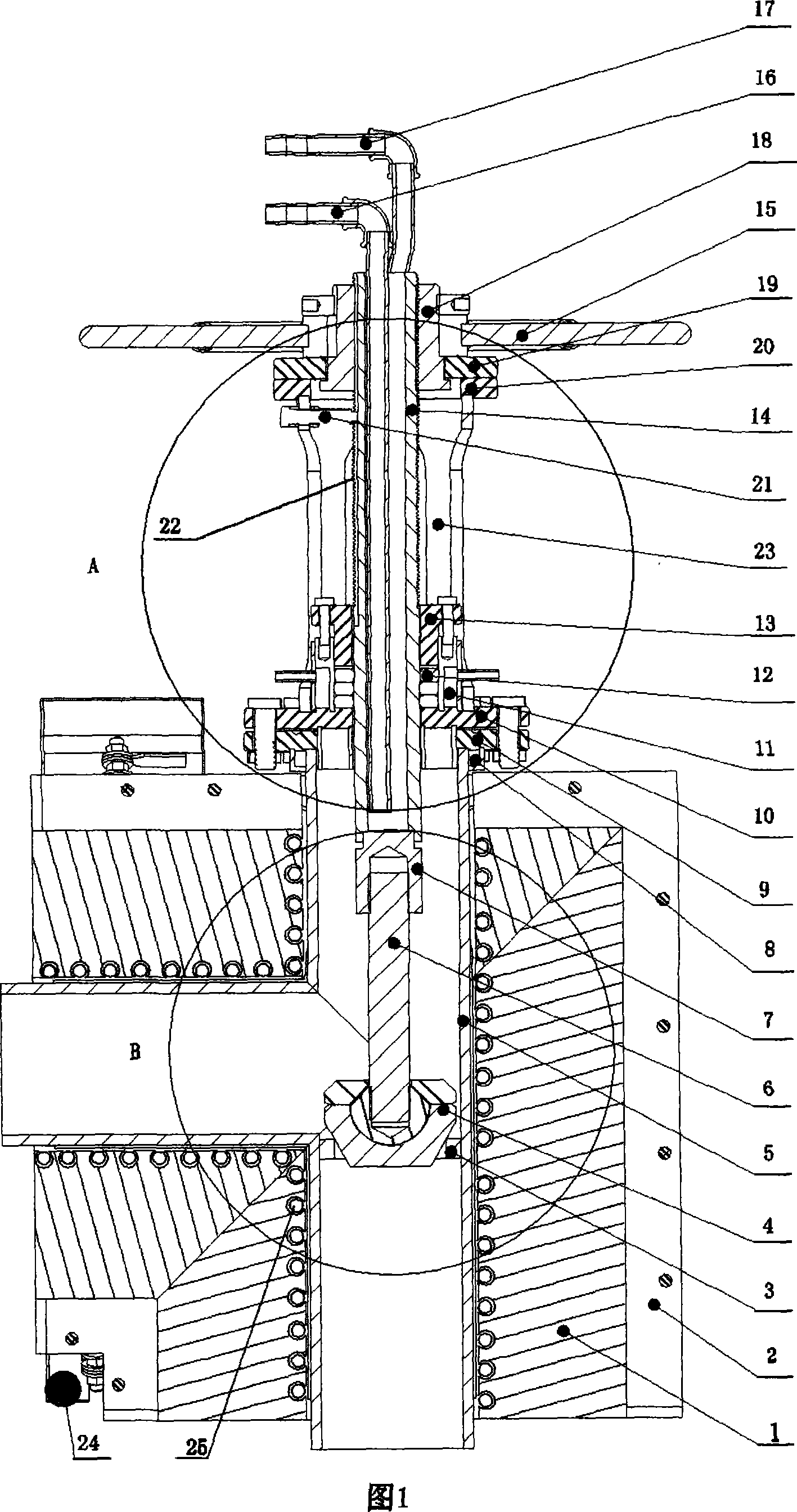
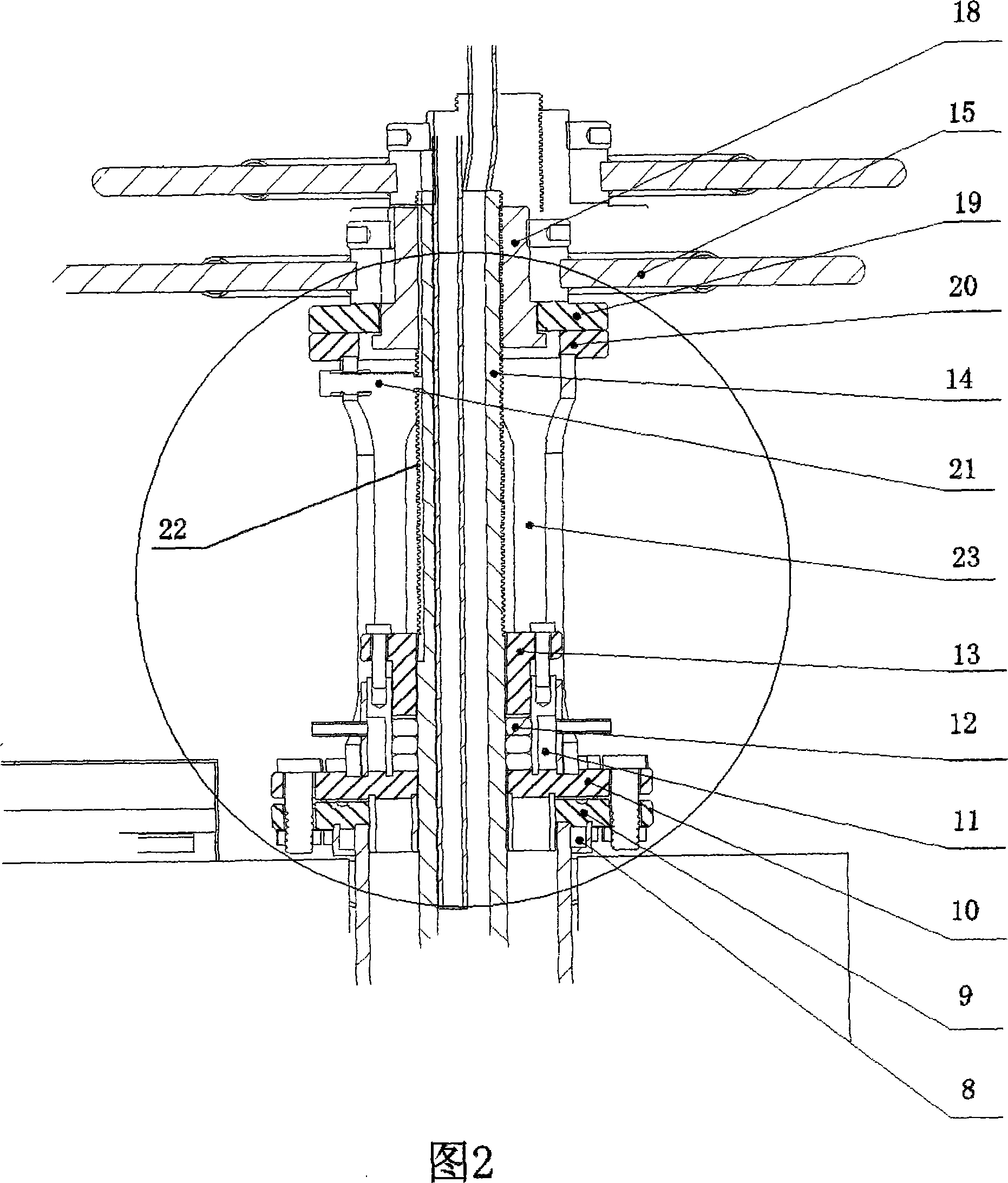
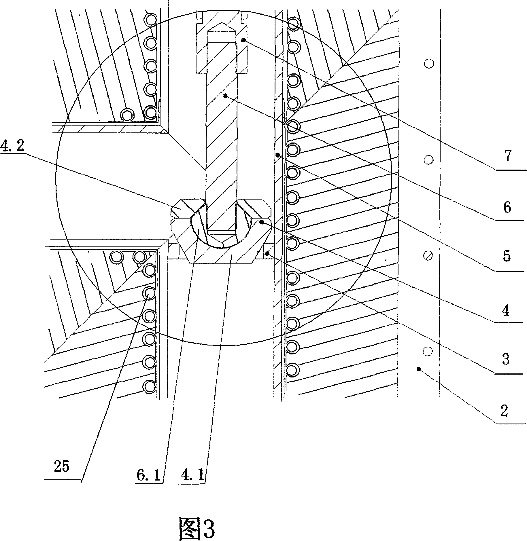
[0008] A heating high-temperature valve, which is installed with a ring valve seat 3 in the valve body 5 of the three-way structure, and a valve body flange 9 with a cooling water jacket 8 is installed on the upper end of the valve body 5, and the valve stem 6 and the transmission mechanism are both Installed on the bracket flange, and then connected to the valve body flange 9 through the lower flange 10 of the bracket flange, a sealing ring 12 and a cooling water jacket 11 are arranged in the flange of the lower flange 10 of the bracket flange, and the sealing ring Compression ring 13 is arranged on the top of 12. The so-called bracket flange is formed by connecting the upper flange 20 and the lower flange 10 by the bracket 23 . A water-cooled lead screw 14 is installed in the bracket flange, and the water-cooled lead screw 14 is connected to the valve stem 6 through the valve stem joint 7, and the lower end of the valve stem 6 is threaded to the valve stem head 6.1, and the ...


PUM


Abstract

A heating hi-temperature valve installed on the connection passage of an equipment, namely a reversed U-like reduction distilling combine furnace, for producing sponge titanium by magnesium method is provided, which comprises a valve body, a heater out the valve body and a valve clack. In the valve body, a circular valve seat is mounted, the valve clack is mounted in a support flange, and is connected with the valve body through a flange. The drive mechanism includes a handwheel, a water-cooled lead screw, a valve-rod connector, a valve rod and a valve clack. The outer surface of the valve clack is conic, is in linear contact with the circular valve seat, so as to guarantee reliable sealing. The heating hi-temperature valve can work under a high temperature up to 1000 centigrade, guarantee free closing, opening and reliable sealing. And as circulating cooling water is provided in the water-cooled lead screw, and cooling water jacket is provided in the flange for cooling the lead screw, the hand wheel is under room temperature, and is easy to operate.

Description

technical field [0001] The invention belongs to the heating high-temperature valve on the connecting corridor of an inverted U-shaped reducing distillation combined furnace for producing sponge titanium by magnesium method. Background technique [0002] In the production process of sponge titanium by magnesium reduction distillation, since the reduction and distillation are carried out in the same heating reactor, it is connected with the parallel condensation tank in the distillation stage, so it is called an inverted U-shaped reduction distillation combined furnace. The reactor used in the reduction process, the evaporator used in the distillation process and the condenser receiving distilled magnesium and magnesium chloride are all interchangeable tank bodies of the same specification. The key to complete the joint production of reduction, distillation, separation and crystallization is to connect the distillation reactor and condenser to form a joint production device th...

Claims


Application Information

Patent Timeline
IPC IPC(8): F16K1/00F16K1/48F16K49/00C22B34/12C22B5/16
Inventor 李家荫吴卫岩
Owner 中信钛业股份有限公司
Why Eureka
Try Eureka