Earth axis type solar furnace optical collector

A solar furnace and concentrator technology, which is applied to solar collectors, solar collector controllers, solar thermal devices, etc., can solve the problems of unsatisfactory light concentrating effect, affecting collection efficiency, and small scale of solar furnaces. Achieve the effect of low cost, high utilization efficiency and increased scale

Inactive Publication Date: 2008-01-23
CHANGCHUN INST OF OPTICS FINE MECHANICS & PHYSICS CHINESE ACAD OF SCI
View PDF0 Cites 13 Cited by
  • Summary
  • Abstract
  • Description
  • Claims
  • Application Information

AI Technical Summary

Problems solved by technology

[0002] Traditional solar furnaces generally use a single parabolic reflector as a concentrator and track the sun through a two-axis drive, always ensuring that the incident direction of sunlight is parallel to the main optical axis, the focus of the concentrator moves with the concentrator, and the receiver is placed at the focus of the concentrator place and move with it, which will inevitably lead to the occlusion of the receiver to the condenser, affecting the collection efficiency
At the same time, due to the follow-up of the receiver and the limitation of its own gravity, the scale of the solar furnace is generally small
The parabolic mirror itself is limited by the surface processing accuracy and tracking accuracy. When the lighting area is too large, the light-gathering effect is not ideal
In addition, the traditional concentrating equipment adopts dual-axis tracking, the control system is complicated, and the cost is high

Method used


Image

  • Earth axis type solar furnace optical collector
  • Earth axis type solar furnace optical collector
  • Earth axis type solar furnace optical collector

Examples


Embodiment Construction

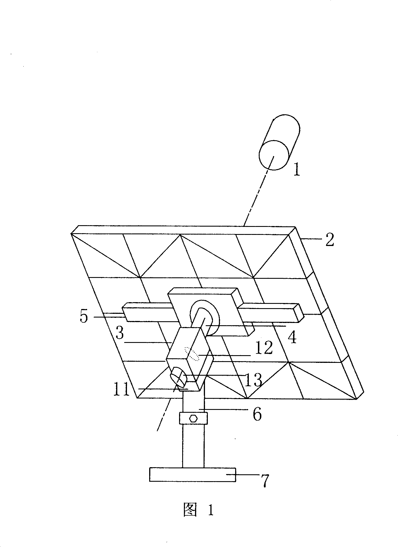
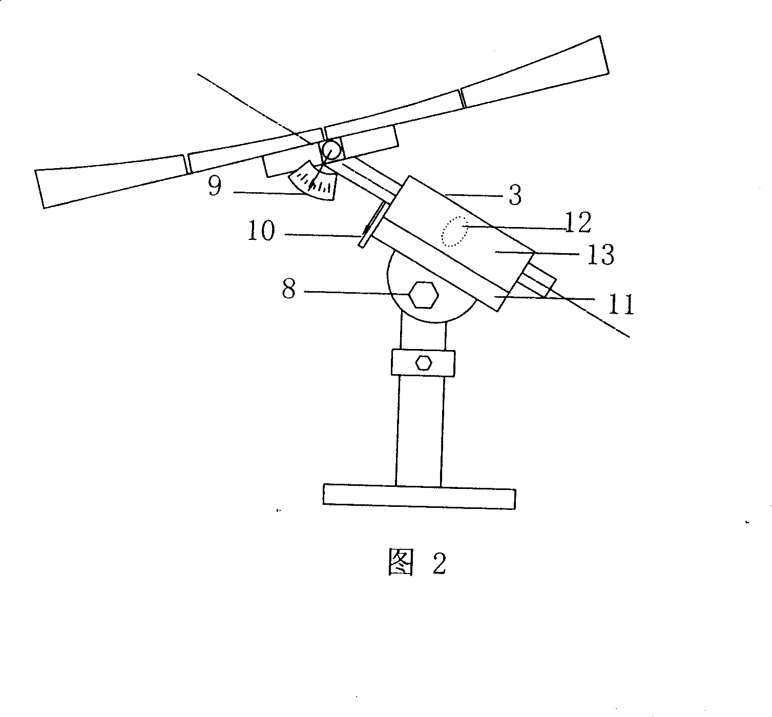
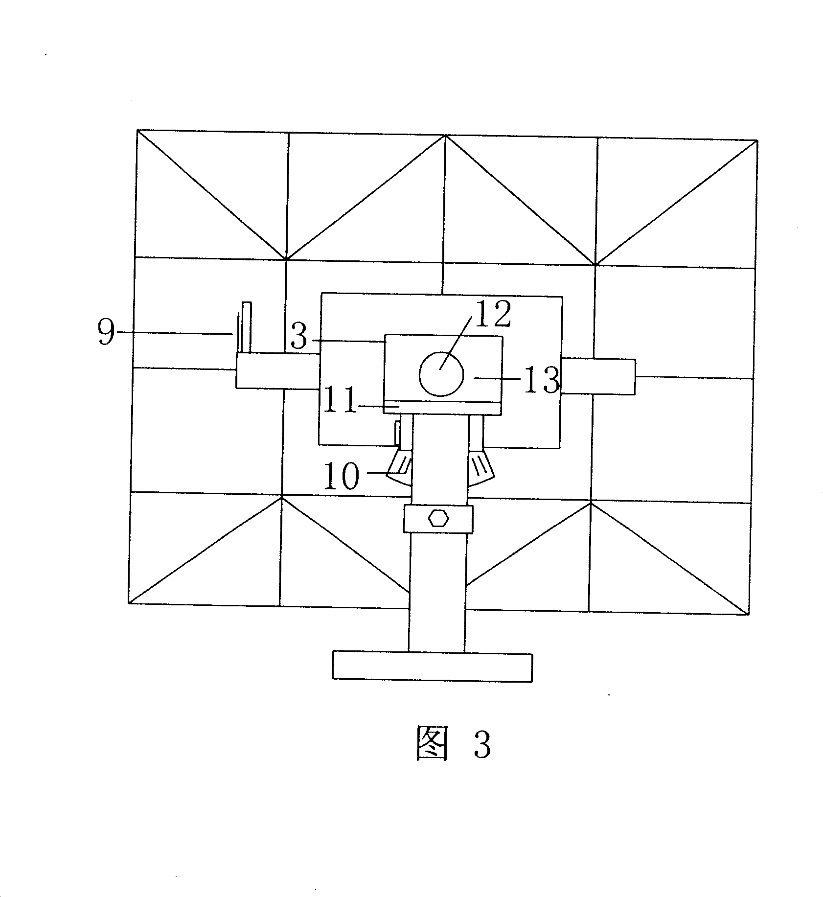
[0027] According to the specific application situation, according to the attached drawings 1, 2, 3, design and manufacture the condenser, and then install and debug.

[0028] 1. Production of the tire surface: The tire surface is a special cylindrical surface. The production method is similar to that of the rotating paraboloid. First, the tire surface scraper curve is made according to the designed tire surface surface formula, and then the tire mold is made by using the scraper. The scraper on the tire surface moves along a fixed track to make the punch. The track is a circular arc whose curvature is equal to that of the sagittal section of the tire surface. Use the prepared convex mold to make the condenser lens. For the condenser lens with a large area, adopt the method of block production, and connect each small piece with a steel bracket on the back of the mirror body. The mirror body can be disassembled and folded, which is convenient for transportation and transportation...


PUM


Abstract

The invention provides an earth-axis type solar light condenser, which pertains to the heat utilization of solar energy. The solar light condenser traces by an earth-axis single axis, guarantees that the sun light is converged on a fixed point on the extended line of the earth axis during the tracing of sun light, and overcomes the shortcomings of prior light condenser such as complex tracing way and the variable condensed target. The rotary shaft of the light condenser is controlled by a synchronous motor, and traces the solar time angle; when the condensing lens is 45 degree to the rotary shaft, the condensing lens is at its zero; the tilt angle of the condensing lens is adjusted periodically so that the angle change of the condensing lens is half of the change in the declination angle. The shape of the condensing lens is a non-rotary symmetric curve allowing the calibration of astigmatism, for example, a tyre surface, which has light-condensing performance higher than spherical surface and parabolic surface, and the manufacturing way is similar to that for a parabolic surface. The light condenser can meet demands from the people in living, for example, boiled water, radiator and air conditioner, etc. By using a secondary light condenser, a high temperature for industrial production can be achieved, for example hydrogen manufacturing by solar energy, etc.

Description

technical field [0001] The invention relates to the thermal utilization technology of solar energy, which is a concentrating device capable of collecting solar energy and is mainly used for heating. Background technique [0002] Traditional solar furnaces generally use a single parabolic reflector as a concentrator and track the sun through a two-axis drive, always ensuring that the incident direction of sunlight is parallel to the main optical axis, the focus of the concentrator moves with the concentrator, and the receiver is placed at the focus of the concentrator It will inevitably cause the receiver to block the condenser and affect the collection efficiency. At the same time, due to the follow-up of the receiver and the limitation of its own gravity, the scale of the solar furnace is generally small. The parabolic mirror itself is limited by the surface processing accuracy and tracking accuracy. When the lighting area is too large, the light-gathering effect is not id...

Claims


Application Information

Patent Timeline
Patent Type & Authority Applications(China)
IPC IPC(8): F24J2/38F24J2/06F24S23/00F24S50/20
CPCY02E10/47Y02E10/44
Inventor 魏秀东卢振武
Owner CHANGCHUN INST OF OPTICS FINE MECHANICS & PHYSICS CHINESE ACAD OF SCI
Why Eureka
Try Eureka