High-voltage automatic change-over switch

An automatic transfer switch, high-voltage technology, applied in high-voltage/high-current switches, electrical switches, power devices inside switches, etc., to achieve the effect of expanding the scope of application and high withstand voltage performance

Active Publication Date: 2008-01-23
NUCTECH CO LTD +1
View PDF0 Cites 6 Cited by
  • Summary
  • Abstract
  • Description
  • Claims
  • Application Information

AI Technical Summary

Problems solved by technology

In the existing high-voltage components, no high-voltage automatic transfer switch that fully meets this application condition has been found.

Method used


Image

  • High-voltage automatic change-over switch
  • High-voltage automatic change-over switch

Examples


Embodiment Construction

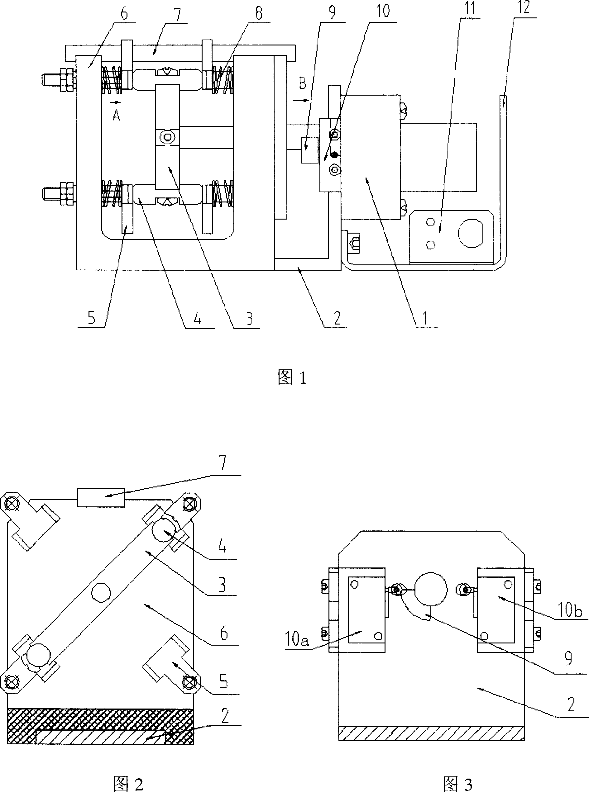
[0023] The specific implementation of the high-voltage automatic transfer switch of the present invention will be further described in detail below in conjunction with the accompanying drawings, but it is not used to limit the scope of protection of the present invention.

[0024] See Figure 1, Figure 2 and Figure 3. The high-voltage automatic transfer switch of the present invention includes a U-shaped insulating frame 6 , an L-shaped mounting frame 2 fixedly connected with the insulating frame 6 , and a J-shaped fixed frame 12 fixedly connected with the mounting frame 2 . In order to ensure the stability of the U-shaped structure, a pull rod 7 made of insulating material is installed at the opening of the U-shaped insulating frame 6 .

[0025] Four spring guide columns are respectively fixed on the two opposite panels of the U-shaped insulating frame 6, and the four spring guide columns on the same panel are arranged in pairs, and the spring guide columns at corresponding po...


PUM


Abstract

The invention relates to a switch, in particular to a high voltage automatic change-over switch comprising a bracket and a control circuit board. Four high voltage contacts are respectively installed on two opposite faceplates on a U-shape insulation support of the bracket; a motor is positioned on the bracket; the output axle of the motor extends inside the U-shape insulation support; two rotors coordinates with the high voltage contacts are respectively at the end section of the motor; a position contact block is positioned on the output axle of the motor; two position limiting switches that coordinate with the position contact block are positioned on the bracket. The beneficial effects of the invention are: capable of resisting the voltage of more than 50KV, allow the passing of pulse current of no less than 500A, excellent contact performance, high stability and capable of automatic change-over. Therefore, the invention, which is able to realize the automatic change-over of power source high voltage in an accelerator system, ensures accelerator to acquire electron flow with different energies, enlarges the application scope of accelerator, thus bringing important significance to the upgrade of industrial non-destructive inspection, customs container detection system and high energy CT system.

Description

technical field [0001] The invention relates to a transfer switch, in particular to a high-voltage automatic transfer switch for a dual-energy or multi-energy electron accelerator system. Background technique [0002] An electron accelerator is a device that accelerates charged particles to very high energy with an electromagnetic field in a vacuum, while an electron linear accelerator is a device that accelerates electrons along a linear orbit with a microwave electromagnetic field. Electron accelerators are widely used in industrial non-destructive testing, customs container testing, high-energy CT and electron beam irradiation and other fields. In electron linear accelerators that use microwave electromagnetic fields to accelerate electrons, in order to obtain high-intensity accelerating electric fields, the instantaneous microwave power is very large and works in the form of pulses. The high-voltage pulse modulator is the main component of this microwave source, mainly ...

Claims


Application Information

Patent Timeline
Patent Type & Authority Applications(China)
IPC IPC(8): H01H31/16H01H3/26H01H1/12H01H1/44
CPCH01H31/20H01H3/22H01H9/40H01H9/54H01H33/14H01H33/28
Inventor 刘耀红陈玉梅唐华平高建军阎忻水高峰贾玮梁笑天刘晋升魏德印炜张丹谷冲张庆辉
Owner NUCTECH CO LTD
Why Eureka
Try Eureka