Module combined type photocatalyst pollutant disposal system

A technology of pollutant treatment and photocatalyst, which is applied in the field of modular combined photocatalyst pollutant treatment system, can solve the problems of not being able to meet the strong treatment of pollutants and weak treatment capacity.

Inactive Publication Date: 2008-01-30
杨小明
View PDF3 Cites 10 Cited by
  • Summary
  • Abstract
  • Description
  • Claims
  • Application Information

AI Technical Summary

Problems solved by technology

[0008] Although the above-mentioned listed patent applications have proposed photocatalyst carrier structures of different structures, they all serve as an important separate component in the photocatalyst pollutant treatment technology, and their processing capacity is higher than that of the photocatalyst carr

Method used


Image

  • Module combined type photocatalyst pollutant disposal system
  • Module combined type photocatalyst pollutant disposal system
  • Module combined type photocatalyst pollutant disposal system

Examples


Embodiment 1

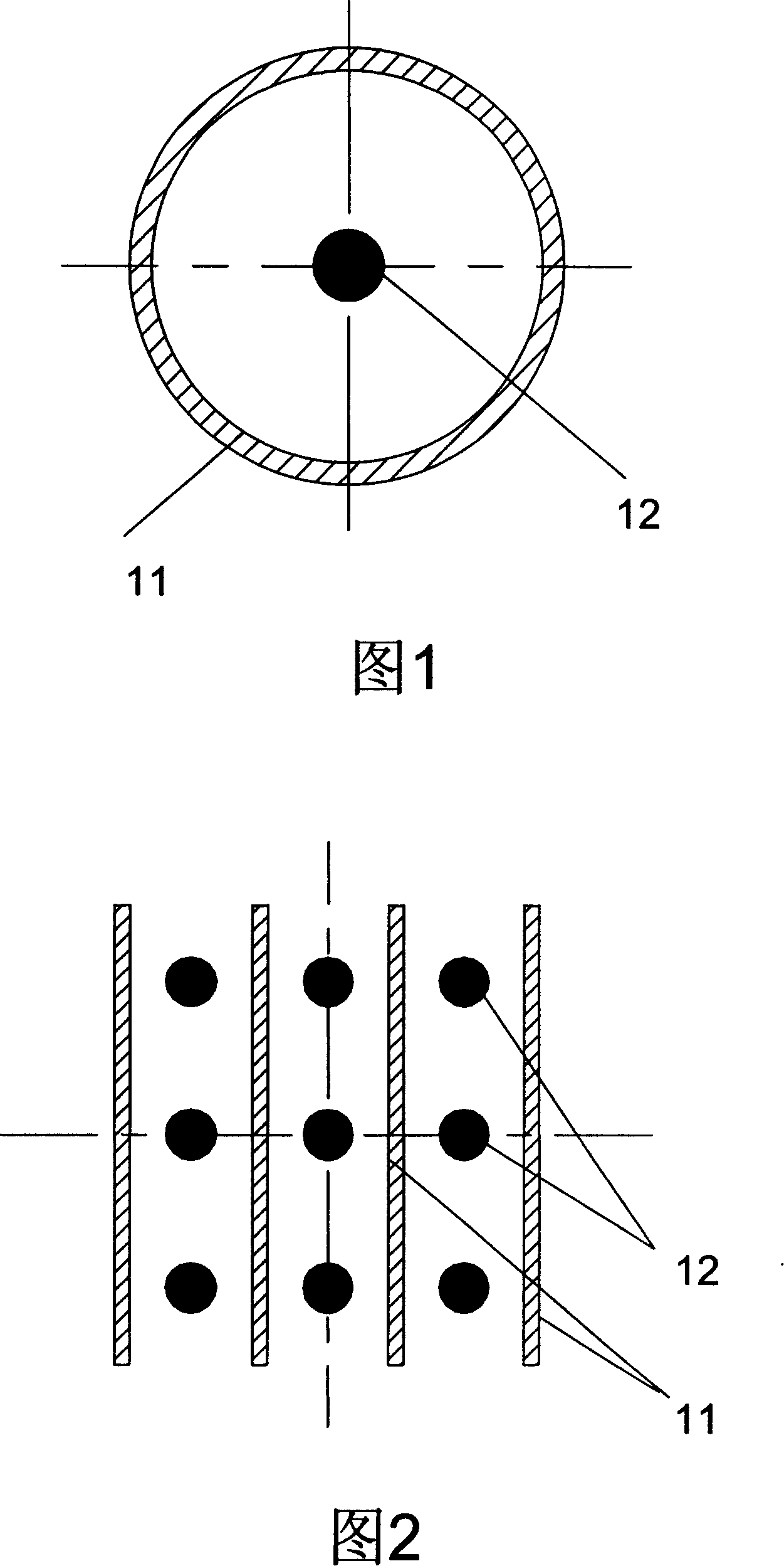
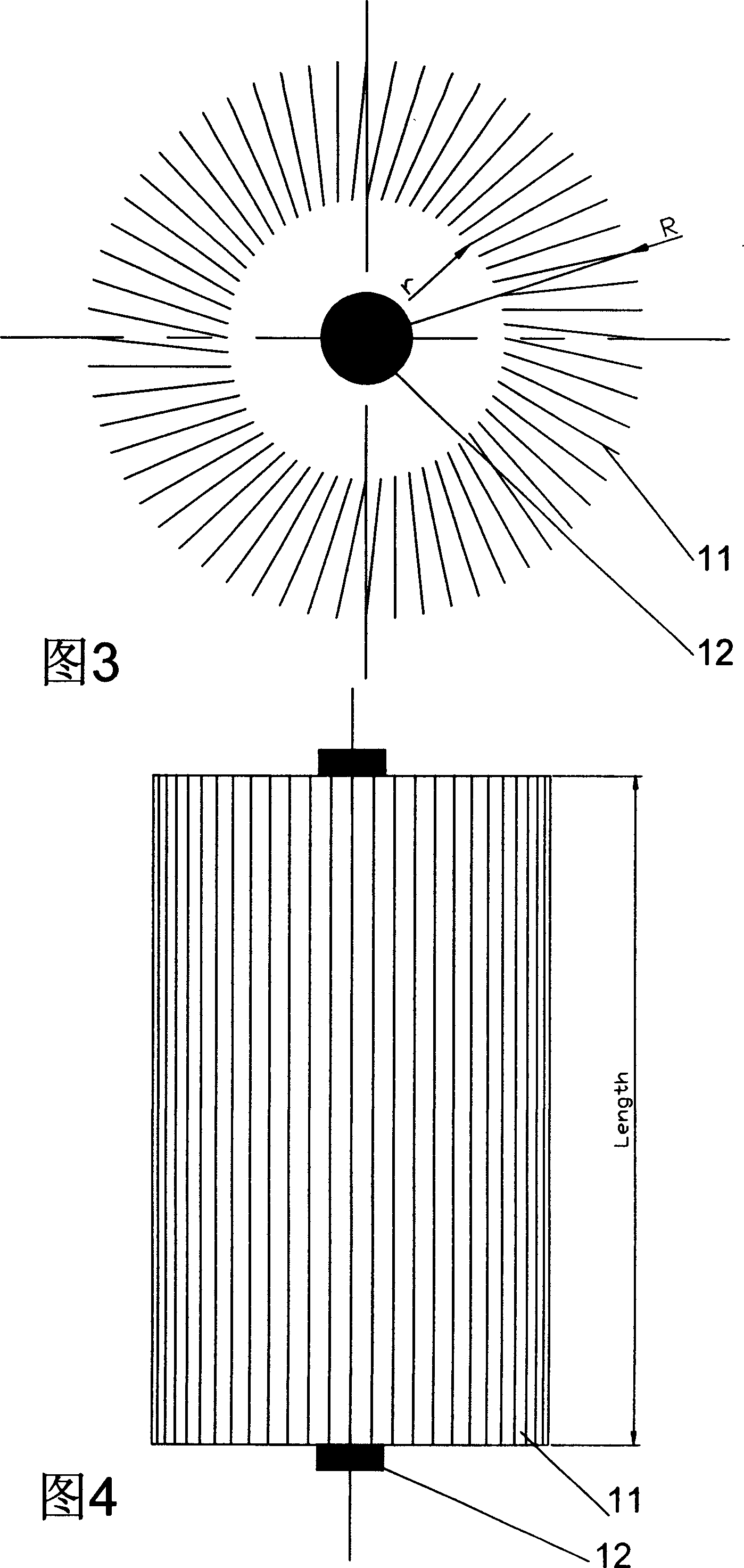
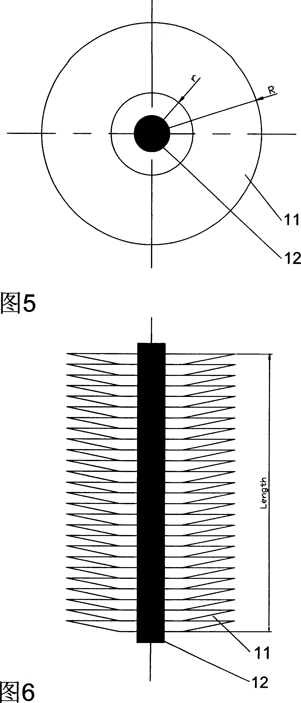
[0040]In the embodiment 1 shown in Fig. 9, photocatalyst carrier structure part 10 is designed as an independent treatment module, and a pollutant treatment system that two independent treatment modules are combined by parallel mode, the flow direction of pollutant fluid is as direction As shown in AB, the so-called parallel connection means that the flow direction of the pollutant fluid flows to two photocatalyst carrier structural components arranged side by side at the same time, in no particular order. The AB flow direction in this embodiment is perpendicular to the ultraviolet lamp tube 12. In FIG. 9, 11 is a photocatalyst carrier, 12 is an ultraviolet lamp tube, and 13 is a housing.

Embodiment 2

[0042] In the embodiment shown in Fig. 10, the photocatalyst carrier structure part 10 is designed as an independent treatment module, and a pollutant treatment system formed by combining two independent treatment modules in series, the flow direction of the pollutant fluid is as direction CD As shown, the so-called series mode, that is, the flow direction of the pollutant fluid flows to two photocatalyst carrier structural components arranged side by side. The flow direction of CD in this embodiment is perpendicular to the ultraviolet lamp tube 12; as shown in Figure 10, 11 is a photocatalyst carrier, 12 is an ultraviolet lamp tube, and 13 is a housing.

Embodiment 3

[0044] In the embodiment shown in Figure 11, as shown in Figure 11, in this example, photocatalyst carrier structure part 10 is designed as an independent processing module, and four independent processing modules are combined by not only parallel but also serial mode In a pollutant treatment system, the flow direction of the pollutant fluid is shown in the direction EF. The so-called series-parallel connection means that there are both series and parallel connections. The upper and lower processing modules are connected in series, and the left and right processing modules are considered to be connected in parallel. . In this embodiment, the flow direction of EF of the pollutant fluid is perpendicular to the ultraviolet lamp 12 . In Fig. 11, 11 is a photocatalyst carrier, 12 is an ultraviolet lamp tube, and 13 is a housing. Each photocatalyst carrier structural part 10 includes a number of photocatalyst carriers 11 and ultraviolet lamp tubes 12 , and the carrier 11 in the pho...


PUM


Abstract

The invention discloses a module combined-typed photocatalyst contamination processing system, which mainly arranges a plurality of photocatalytic carrier structure parts in a shell in the serial way or parallel way or serial and parallel way to constitute the photocatalyst contamination processing system. The contamination processing system can be combined in serial and/or parallel way by selecting and using independent processing modules with suitable quantity according to the design scale of the contamination processing system. The invention simplifies and facilitates the design of the photocatalyst contamination processing system which is the same convenient as the module combination. The contamination processing system with modularization design not only can increase the processing ability of the processing system to the contamination according to the requirement, but also can improve the circulation path of the contamination processing by simple modularization combination, and improve the stopping time of the contamination fluid in the processing system, namely the contacting reaction time with the photocatalyst carrier, thus obtaining more effective contamination processing system.

Description

technical field [0001] The invention relates to filtering and treating pollutant fluids, and more specifically refers to a modular combined photocatalyst pollutant treating system. Background technique [0002] The photocatalytic properties of photocatalysts (such as nano-titanium dioxide) were discovered by Professor Fujiyu Akira in Japan in 1972, and have been extensively studied and applied so far. The basic principle of photocatalysis is: when semiconductor oxide (such as titanium dioxide) nanoparticles are irradiated by photons (such as ultraviolet light) with energy greater than the forbidden band width, electrons transition from the valence band to the conduction band, generating electron-hole pairs. Electrons are reducing, and holes are oxidizing. Holes react with OH- on the surface of oxide semiconductor nanoparticles to generate highly oxidizing OH radicals. Active OH radicals can oxidize many refractory organic compounds into CO2 and Inorganic substances such as ...

Claims


Application Information

Patent Timeline
IPC IPC(8): B01J19/12
Inventor 杨小明
Owner 杨小明
Why Eureka
Try Eureka