Drying machine

A dryer and drying chamber technology, applied in the invention field of dryers, can solve problems such as user inconvenience, dryer performance degradation, and insufficient air flow, and achieve the effects of ensuring reliability and preventing performance degradation

Inactive Publication Date: 2008-01-30
NANJING LG PANDA APPLIANCES
View PDF5 Cites 5 Cited by
  • Summary
  • Abstract
  • Description
  • Claims
  • Application Information

AI Technical Summary

Problems solved by technology

[0015] However, due to the continuous driving of the dryer, when excessive foreign matter is generated, the user needs to clean the lint filter, thus causing inconvenience to the user.
Also, if the lint filter is not cleaned due to the negligence of the user, the

Method used


Image

  • Drying machine
  • Drying machine

Examples


Embodiment Construction

[0037] Below in conjunction with the accompanying drawings and preferred embodiments, the specific implementation, structure, features and effects of the present invention will be described in detail as follows.

[0038] ***Description of symbols for main components in the drawings***

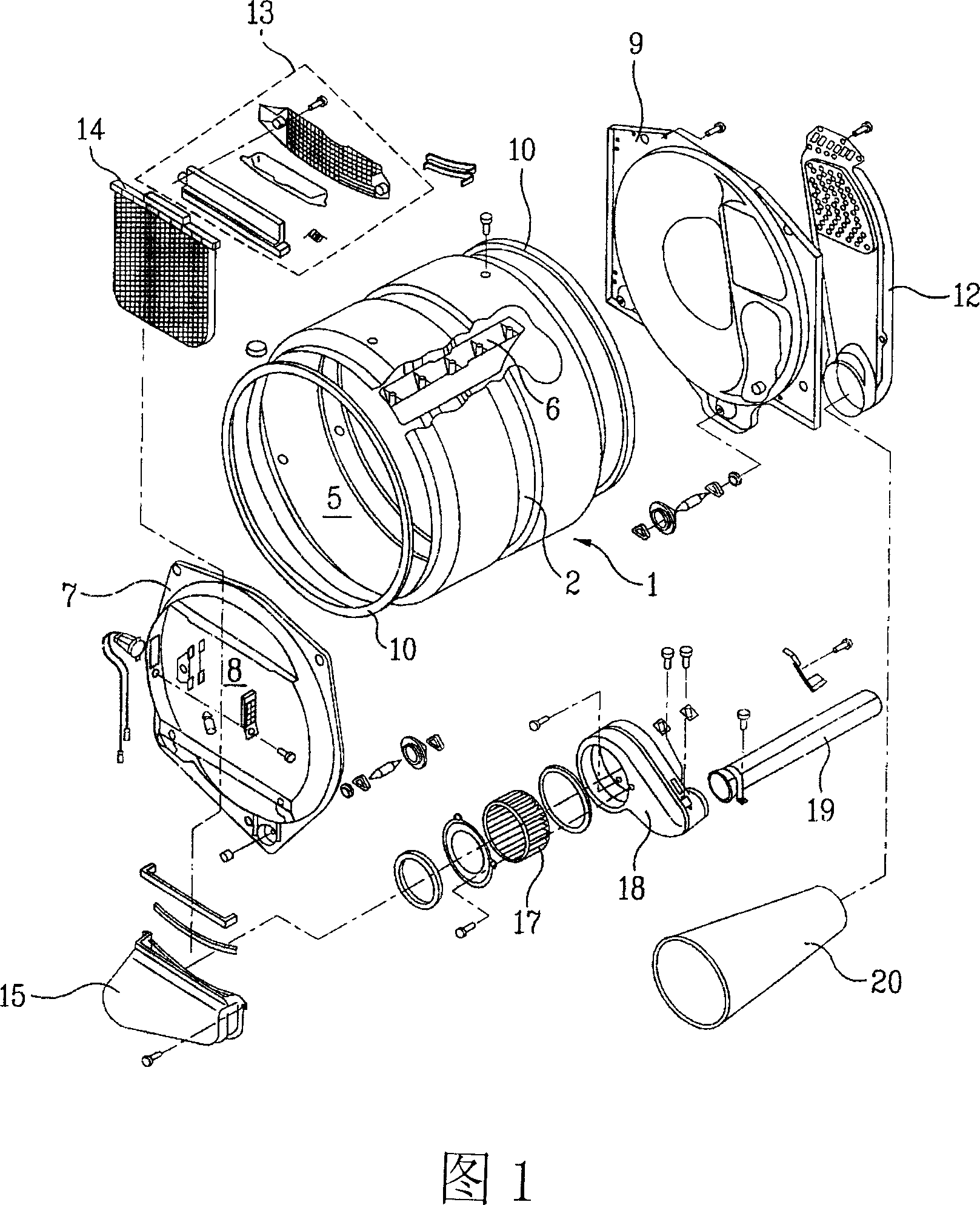
[0039] 1: drum 5: drying chamber

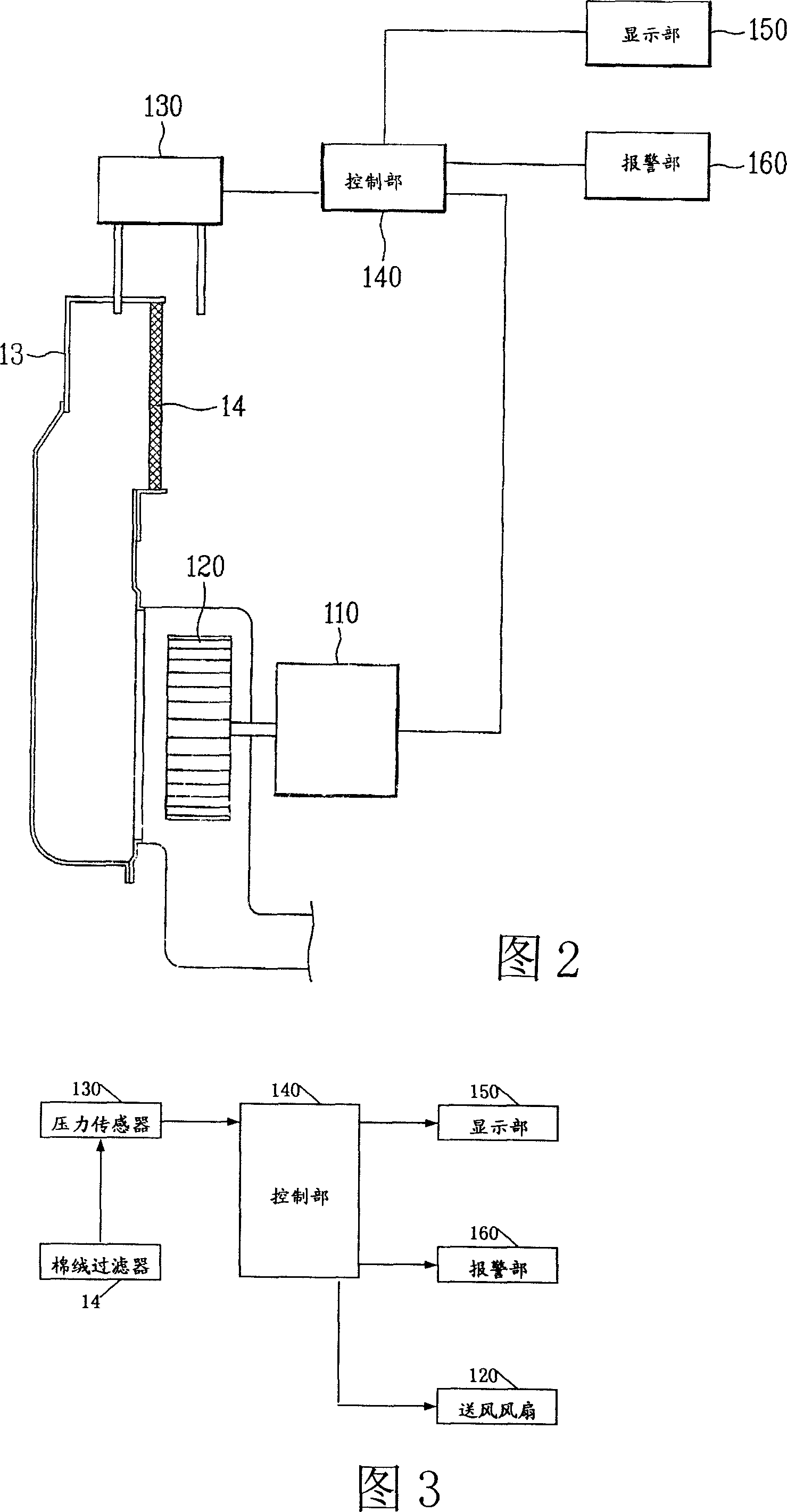
[0040] 14: Lint filter 15: Lint duct

[0041] 110: Drive motor 120: Blowing fan

[0042]130: Pressure sensor 140: Control unit

[0043] 150: display unit 160: alarm unit (alarm)

[0044] In addition, the same reference numerals as in FIG. 1 refer to components having the same functions, and only the characteristic parts of the present invention will be described.

[0045] Referring to Fig. 2 and Fig. 3, the dryer of the present invention is composed of the following parts: a drum 1 with a drying chamber 5; for filtering the air discharged from the drying chamber 5 of the drum 1 The lint filter 14 of the foreign matter in the lint filter; the lint air chan...


PUM


Abstract

The invention relates to a dryer, comprising the components: a drum with a drying cavity, a lint filter used for filtering foreign matters drained out of the drying cavity of the drum and a lint air duct for the air of the lint filter to flow. An air supply fan is arranged and communicated with the lint filter. And the air supply fan, under the drive of a driving motor, ensures the air in the drying cavity to flow through the lint filter. A pressure sensor is arranged to check the pressure difference of the lint filter outside and inside. By receiving the sensor signals sent from the pressure sensor, and under the condition of the pressure difference rising above the standard value, the pollution caused by lint filter blocking can be solved through controlling the driving motor and increasing the controlling part of the rotating number of the air supply fan, ensuring the air in the drying cavity to flow more smoothly, thus improving the performance of the dryer.

Description

technical field [0001] The present invention relates to a drying device, more specifically to an invention of a dryer which solves the pollution caused by the clogging of the lint filter and makes the air flow inside the dryer more smooth, thereby improving the drying performance . Background technique [0002] The structure of the general dryer is described below with reference to the disassembled oblique view of the prior art dryer. As shown in Figure 1, the appearance of the dryer according to the prior art is made of a shell (not prompted in the figure), and the above shell The inside of the body is provided with a drum 1 . [0003] The above-mentioned drum 1 has a cylindrical shape, and its both ends are open. Moreover, a belt groove 2 is formed along the middle part of the outer peripheral surface, and a belt (not shown in the figure) is wound in the belt groove, and the belt will be driven by another driving source. A drying cavity 5 for drying operation is formed ...

Claims


Application Information

Patent Timeline
IPC IPC(8): F26B11/02F26B25/00F26B25/04
Inventor 李岱来柳廷玩金英洙金良镐
Owner NANJING LG PANDA APPLIANCES
Why Eureka
Try Eureka