Analyzing electromagnet

An electromagnet and magnetic pole technology, applied in the field of electromagnet analysis, can solve the problems of complex structure, uniformity of damage process, etc., and achieve the effect of simple structure, easy adjustment, and small number of divisions

Active Publication Date: 2008-01-30
NISSIN ION EQUIP CO LTD
View PDF2 Cites 4 Cited by
  • Summary
  • Abstract
  • Description
  • Claims
  • Application Information

AI Technical Summary

Problems solved by technology

[0018] In addition to the above-mentioned problems in the analysis slit 20, there arises a problem that when a process such as ion implantation is applied to a target (such as a semiconductor substrate or a glass substrate) by using the ion beam 2 having a shape distorted as described above, Uniformity of damage process
However, there is another problem: the complex structure

Method used


Image

  • Analyzing electromagnet
  • Analyzing electromagnet
  • Analyzing electromagnet

Examples


Embodiment Construction

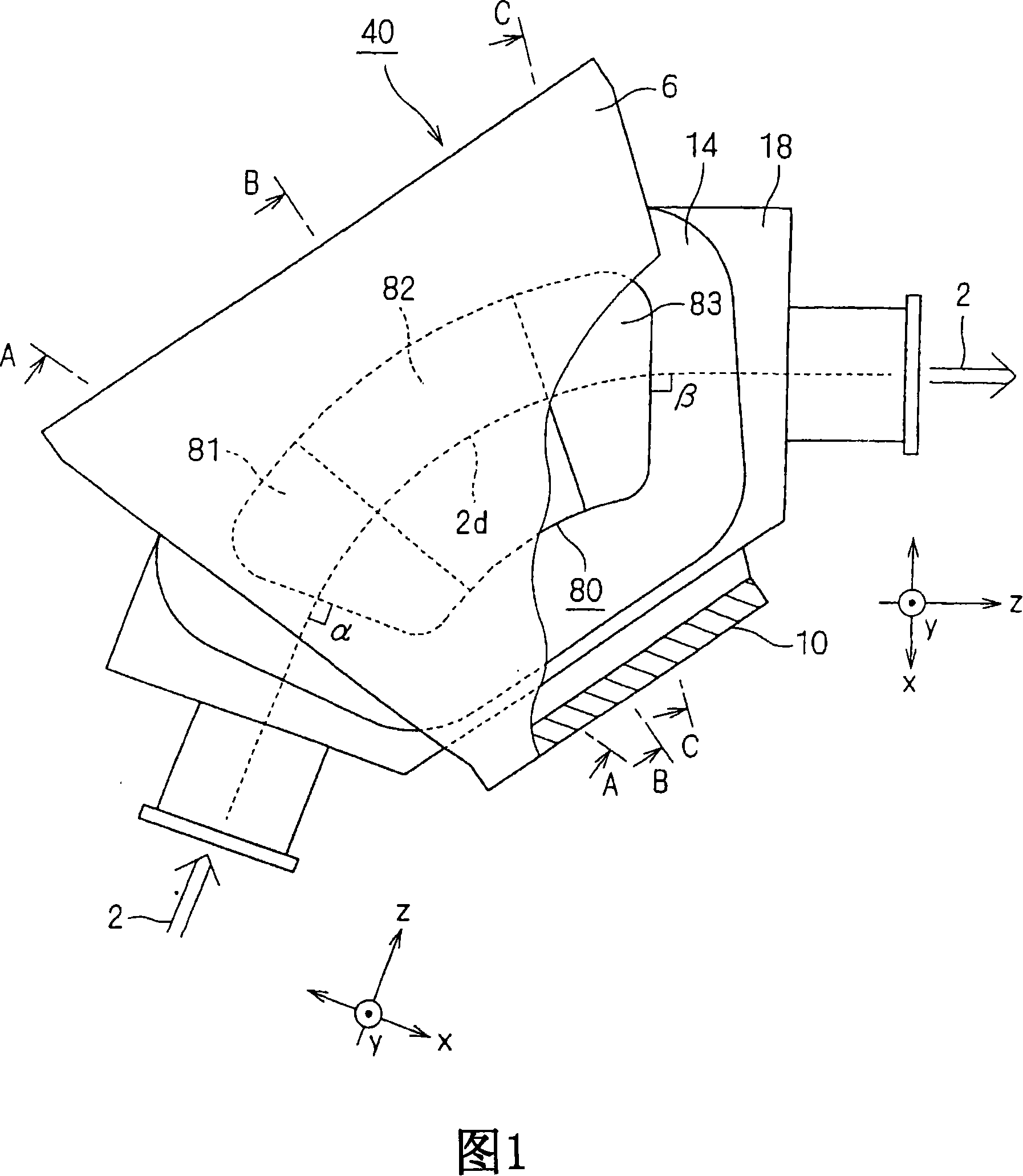
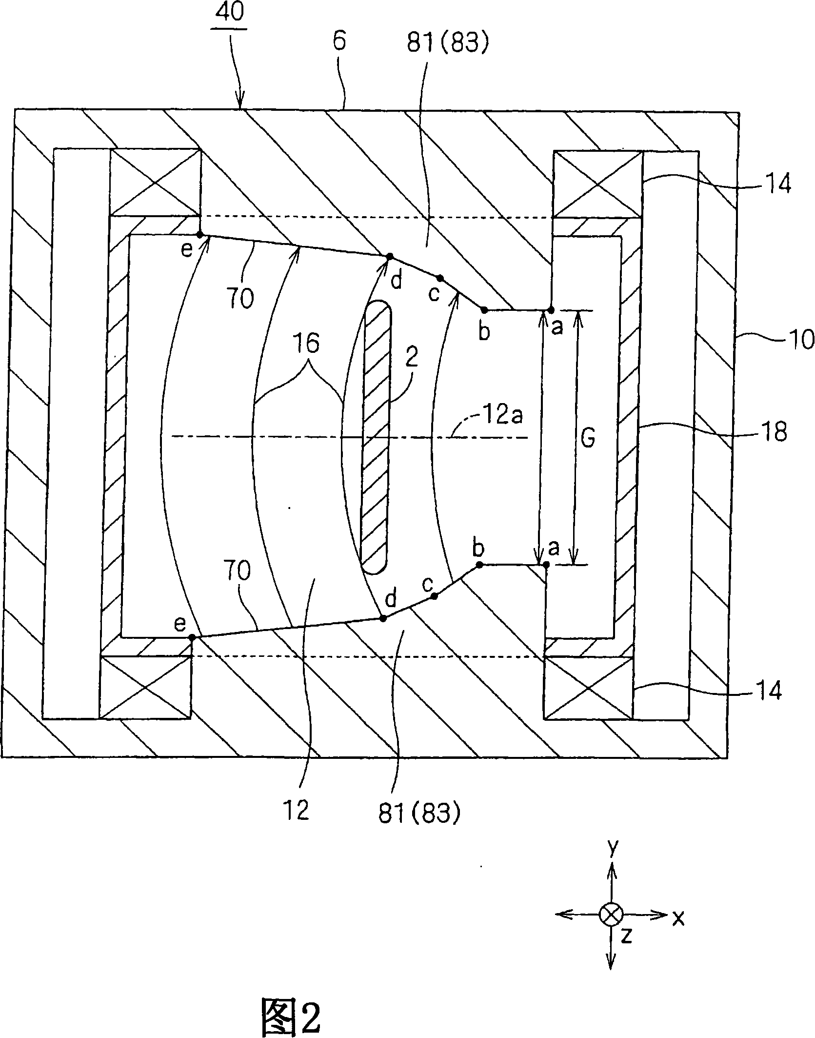
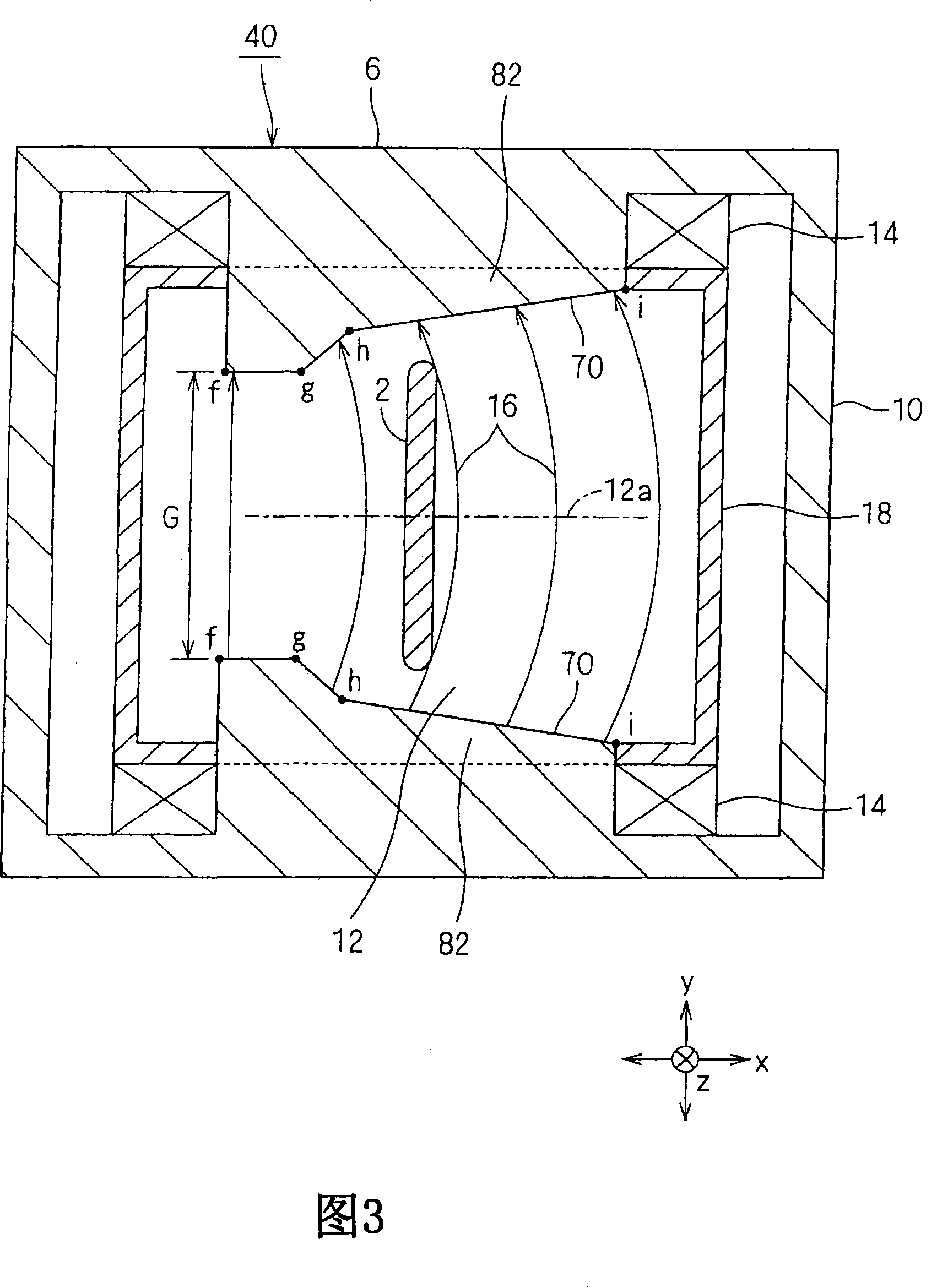
[0050] Fig. 1 is a plan view showing an embodiment of an analyzing electromagnet of the present invention. Components that are the same as or equivalent to those of the prior art shown in FIGS. 11 and 12 are denoted by the same reference numerals, and the following description is made by focusing on points different from the prior art example.

[0051] The analyzing electromagnet 40 comprises a magnetic pole 80 instead of the magnetic pole 8 constituting the prior art analyzing electromagnet 4 . The ion beam 2 having a ribbon shape extending in the y direction is incident on the gap of the magnetic pole 80 . The plan view shape of each of the magnetic poles 80 is bent into a sector shape. The central trajectory of the ion beam 2 which will pass through the analyzing electromagnet 40 is indicated by reference numeral 2d. In this embodiment, the incident angle α of the ion beam 2 to the magnetic pole 80 and the exit angle β of the ion beam 2 from the magnetic pole 80 are set t...


PUM


Abstract

In the analysis electromagnet 40 , each of the magnetic poles having a curved plan view shape therein is divided into three partial magnetic poles 81 to 83 along the propagation direction of the ion beam 2 . Towards the outside of the bend, the gap of the first and third partial pole pairs 81, 83 as counted from the entrance of the ion beam 2 widens, and towards the inside of the bend, the gap of the second partial pole pair 82 widens.

Description

[0001] This application claims priority from Japanese Patent Application No. 2006-160991 filed on Jun. 9, 2006 at the Japan Patent Office. This priority application is hereby incorporated by reference in its entirety. technical field [0002] The present disclosure relates to an analysis electromagnet to be used in an ion implantation apparatus, an ion doping (registered trademark) apparatus, etc. and to deflect an ion beam so as to perform momentum analysis of the ion beam, and more particularly, to analysis of a ribbon ion beam Momentum analysis of electromagnets. Background technique [0003] For example, Patent Document 1 (UM-A-64-7753 (FIG. 1)) discloses an example of a related art analysis electromagnet that deflects an ion beam in order to perform momentum analysis (such as mass analysis) of the ion beam, and hereinafter the same applies ). [0004] 11 shows that, in the analytical electromagnet of this related art, between magnetic poles in which the shape of the c...

Claims


Application Information

Patent Timeline
Patent Type & Authority Applications(China)
IPC IPC(8): H01J49/02H01J37/02H01J37/244
CPCH01J2237/057H01J2237/152H01J37/1475H01J2237/055H01J49/30H01J2237/153H01J2237/31701H01F7/06
Inventor 土肥正二郎
Owner NISSIN ION EQUIP CO LTD
Why Eureka
Try Eureka