Crown gear train type spacing mechanical arm modularization joint

A space manipulator, modular joint technology, applied in manipulators, manufacturing tools, joints, etc., can solve the problems of low output torque per unit mass, high power consumption, high mass, etc., and achieve high overall stiffness, low power consumption, and high quality. light effect

Inactive Publication Date: 2008-02-06
HARBIN INST OF TECH
View PDF0 Cites 8 Cited by
  • Summary
  • Abstract
  • Description
  • Claims
  • Application Information

AI Technical Summary

Problems solved by technology

[0003] In order to solve the problems of large volume, large mass, large power consumption, and small output torque per unit mass, the present invention provides a crown Modular joint of gear train space manipulator

Method used


Image

  • Crown gear train type spacing mechanical arm modularization joint
  • Crown gear train type spacing mechanical arm modularization joint
  • Crown gear train type spacing mechanical arm modularization joint

Examples


specific Embodiment approach 1

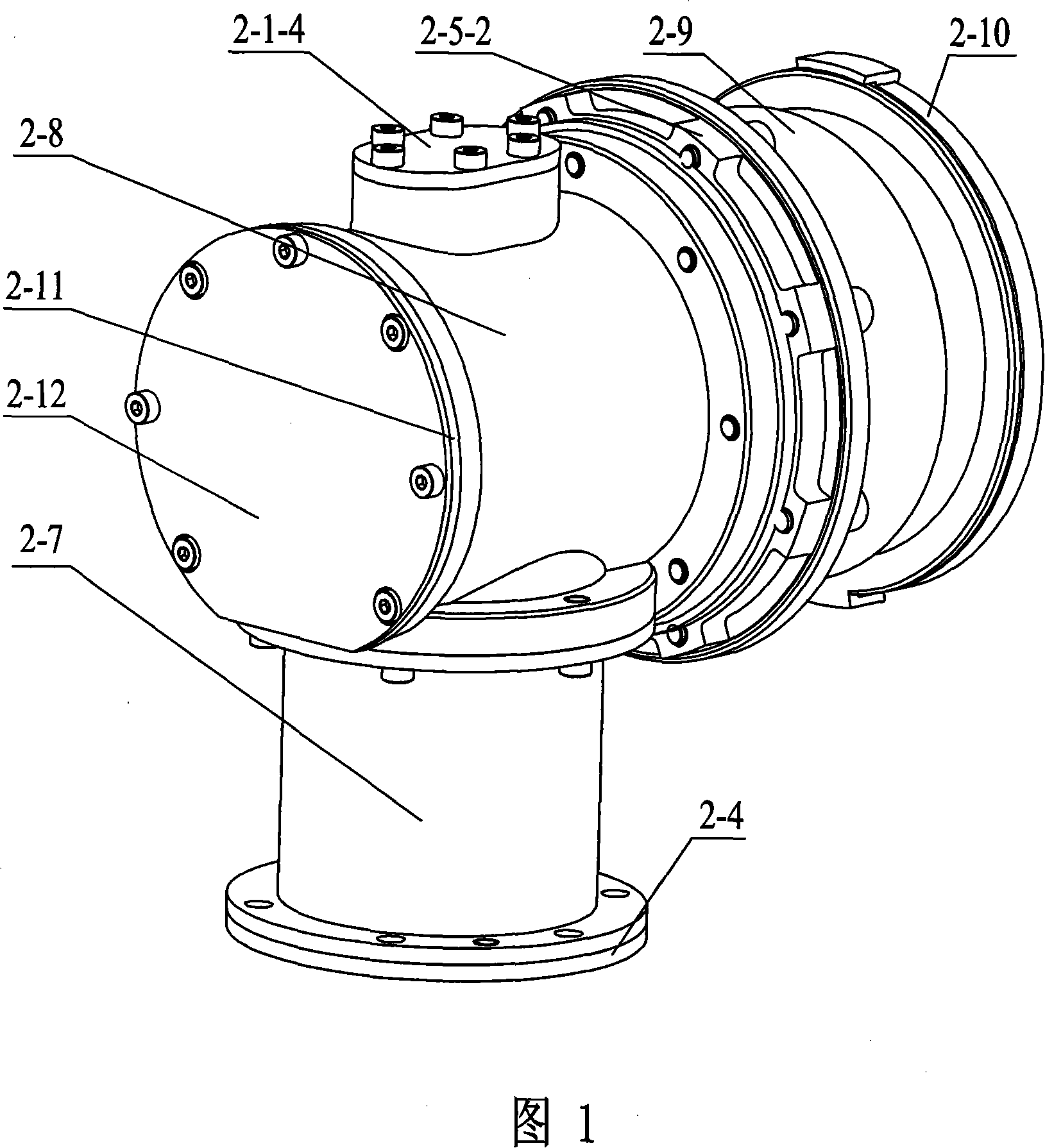
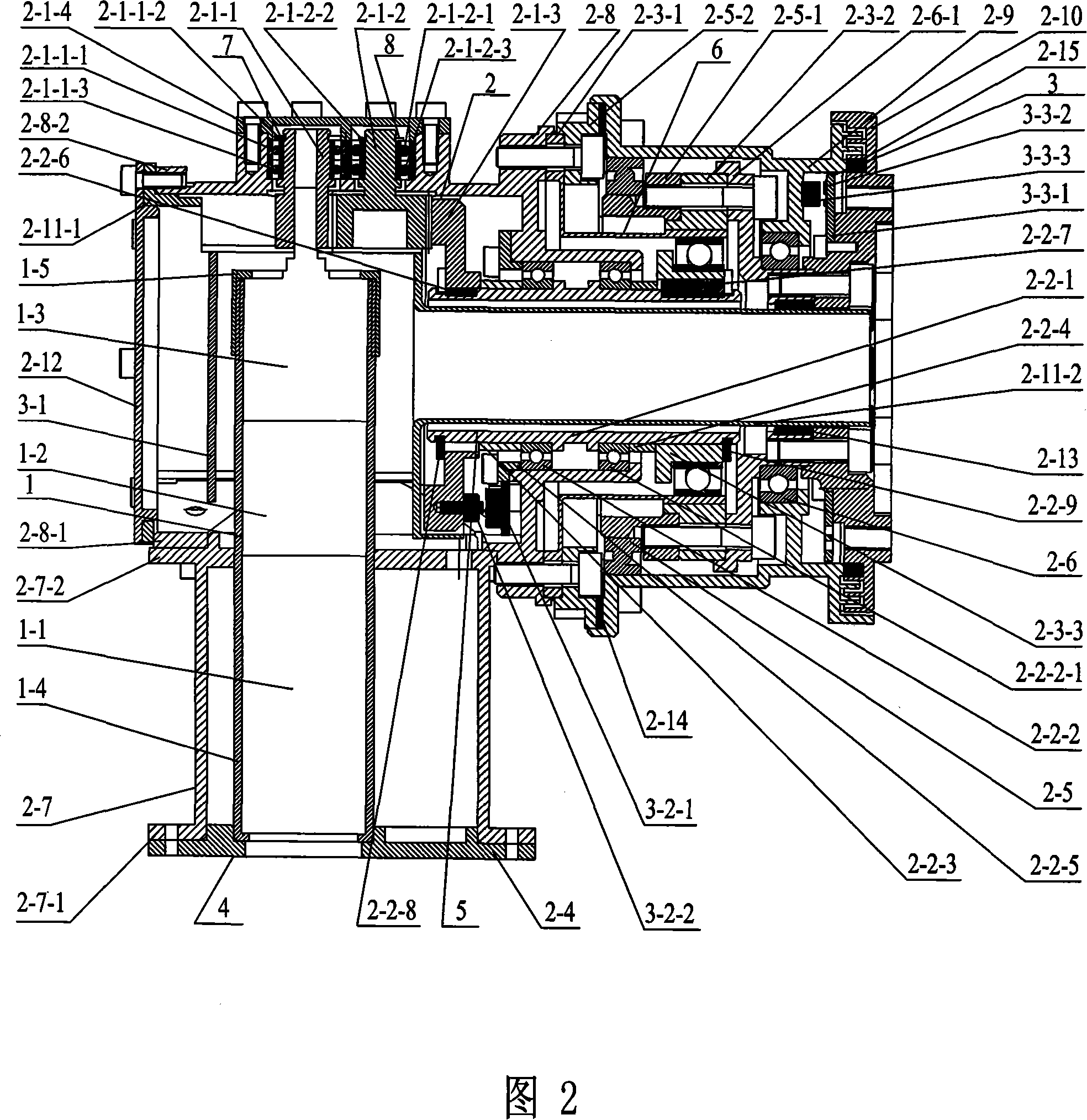
[0007] Specific Embodiment 1: As shown in Fig. 1, Fig. 2, Fig. 4-10, the modular joint of the crown gear train type space manipulator in this embodiment consists of an outer casing 4, a driving device 1, a joint mechanism 2 and an electrical device 3 Composition, the drive device 1, the joint mechanism 2 and the electrical device 3 are all installed in the outer shell 4, the drive device 1 is connected to the joint mechanism 2, and the electrical device 3 is arranged on the joint mechanism 2; the described joint mechanism 2 is composed of Crown pinion 2-1-1, crown idler 2-1-2, crown gear 2-1-3, first bearing assembly 7, second bearing assembly 8, crown gear system pressure plate 2-1-4 , Hollow transmission shaft device 5, harmonic reducer 6, large thin-wall bearing 2-5, small thin-wall bearing 2-6, large thin-wall bearing inner ring support seat 2-5-1, large thin-arm bearing outer ring stop Ring 2-5-2, small thin-wall bearing inner ring support seat 2-6-1, sleeve 2-11; the sle...

specific Embodiment approach 2

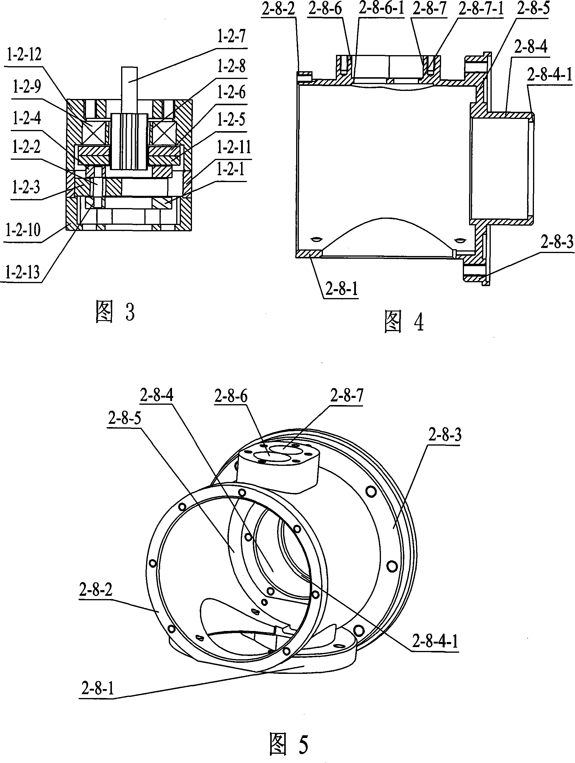
[0009] Specific embodiment two: as shown in Fig. 1, Fig. 2, Fig. 4-10, the outer casing 4 described in this embodiment is composed of a first casing 2-7, a second casing 2-8, and a third casing 2-9. , joint rear end cover 2-12, output flange 2-10, motor sleeve fixing base 2-4, the No. 2 flange 2-7 of the first shell on the upper end of the first shell 2-7 -2 is connected with the No. 1 flange plate 2-8-1 of the second shell on the lower side wall of the second shell 2-8, and the No. 3 flange plate 2-8 of the second shell on the right end of the second shell 2-8 -3 is connected with the No. 1 flange plate 2-9-1 of the third housing at the left end of the third housing 2-9, and the motor sleeve fixed base 2-4 is connected with the No. 1 housing No. 1 at the lower end of the first housing 2-7. The flange plate 2-7-1 is connected, the joint rear end cover 2-12 is connected with the second shell No. 2 flange plate 2-8-2 on the left end of the second shell 2-8, and the output flange...

specific Embodiment approach 3

[0010] Specific embodiment three: As shown in Figure 2, the drive device 1 described in this embodiment consists of a brushless DC motor 1-1, a friction reverse brake 1-2, a planetary reducer 1-3, and a motor sleeve 1- 4 and the motor sleeve cover 1-5, the motor sleeve 1-4 is fixed on the motor sleeve fixed base 2-4, the DC brushless motor 1-1, the friction reverse brake 1- 2. The planetary reducer 1-3 is installed in the motor sleeve 1-4 sequentially from bottom to top, the output end of the DC brushless motor 1-1 is connected to the input end of the friction reverse brake 1-2, and the friction reverse brake The output end of the brake 1-2 is connected to the input end of the planetary reducer 1-3, the motor sleeve cover 1-5 is fixed on the upper end of the motor sleeve 1-4, and the motor sleeve 1-4 is made of titanium alloy material. Both the rear end of the motor sleeve and the inside of the motor sleeve cover are threaded, and the two can be screwed tightly, which is easy...


PUM


Abstract

The invention provides a crown / Rolex gear series modular joint for space manipulator, relating to a modular joint for space manipulator. The invention solves the problems with the prior modular joint for space manipulator which is big in size, mass and power consumption but small in output torque of unit mass. A crown / Rolex small gear (2-1-1) is connected with the output end of a planet reducer (1-3) in a driving device, a first bearing assembly (7) is arranged on the crown / Rolex small gear (2-1-1), a second bearing assembly (8) is arranged on a crown / Rolex idler wheel (2-1-2), the crown / Rolex small gear (2-1-1) and the crown / Rolex idler wheel (2-1-2) are meshed together and are connected with a second outer shell (2-8) on an outer shell unit (4) via a crown / Rolex gear series press board (2-1-4), the crown / Rolex idler wheel (2-1-2) and a crown / Rolex big gear (2-1-3) are meshed together and the crown / Rolex big gear (2-1-3) is connected with the output end of a hollow transmission shaft (2-2-1) in a hollow transmission shaft device. The invention has the advantages of high in safety, good in reliability, big in output torque, high in position output precision and simpler in structure.

Description

technical field [0001] The invention relates to a space manipulator modular joint. Background technique [0002] In the past ten or twenty years, my country's space technology has developed rapidly. In the future, my country will establish its own space station in space. Space robots are required to perform tasks such as the construction and maintenance of space stations, and the release, maintenance and recovery of satellites. However, space robots currently It is not yet possible to complete these tasks. In the near future, our country will explore the moon, Mars and even other celestial bodies, and some operations in space are required, and these operations are inseparable from the space robotic arm. The modular joint is an important part of the space manipulator, and the performance of the modular joint determines the main performance of the whole manipulator. At present, many research institutes and universities at home and abroad are conducting related research. Acco...

Claims


Application Information

Patent Timeline
Patent Type & Authority Applications(China)
IPC IPC(8): B25J17/00B25J13/00B25J19/00
Inventor 刘宏李德伦谢宗武孙奎熊根良
Owner HARBIN INST OF TECH
Why Eureka
Try Eureka