Planar lightwave circuit based wavelength selective switch
What is Al technical title?
Al technical title is built by PatSnap Al team. It summarizes the technical point description of the patent document.
A planar lightwave circuit and wavelength channel technology, applied in the WSS field, can solve the problems of the light path being in the air, extremely sensitive to misalignment, and expensive.
Inactive Publication Date: 2008-02-06
JDS UNIPHASE CORP
View PDF8 Cites 14 Cited by
Summary
Abstract
Description
Claims
Application Information
AI Technical Summary
This helps you quickly interpret patents by identifying the three key elements:
Problems solved by technology
Method used
Benefits of technology
Problems solved by technology
Thus, not only does the external lens need to be extremely well calibrated (ie relatively expensive and extremely sensitive to misalignment), but also the majority of the optical path must be in air
Method used
Image
Click on the blue label to locate the original text in one second.
Reading with bidirectional positioning of images and text.
Examples
Embodiment Construction
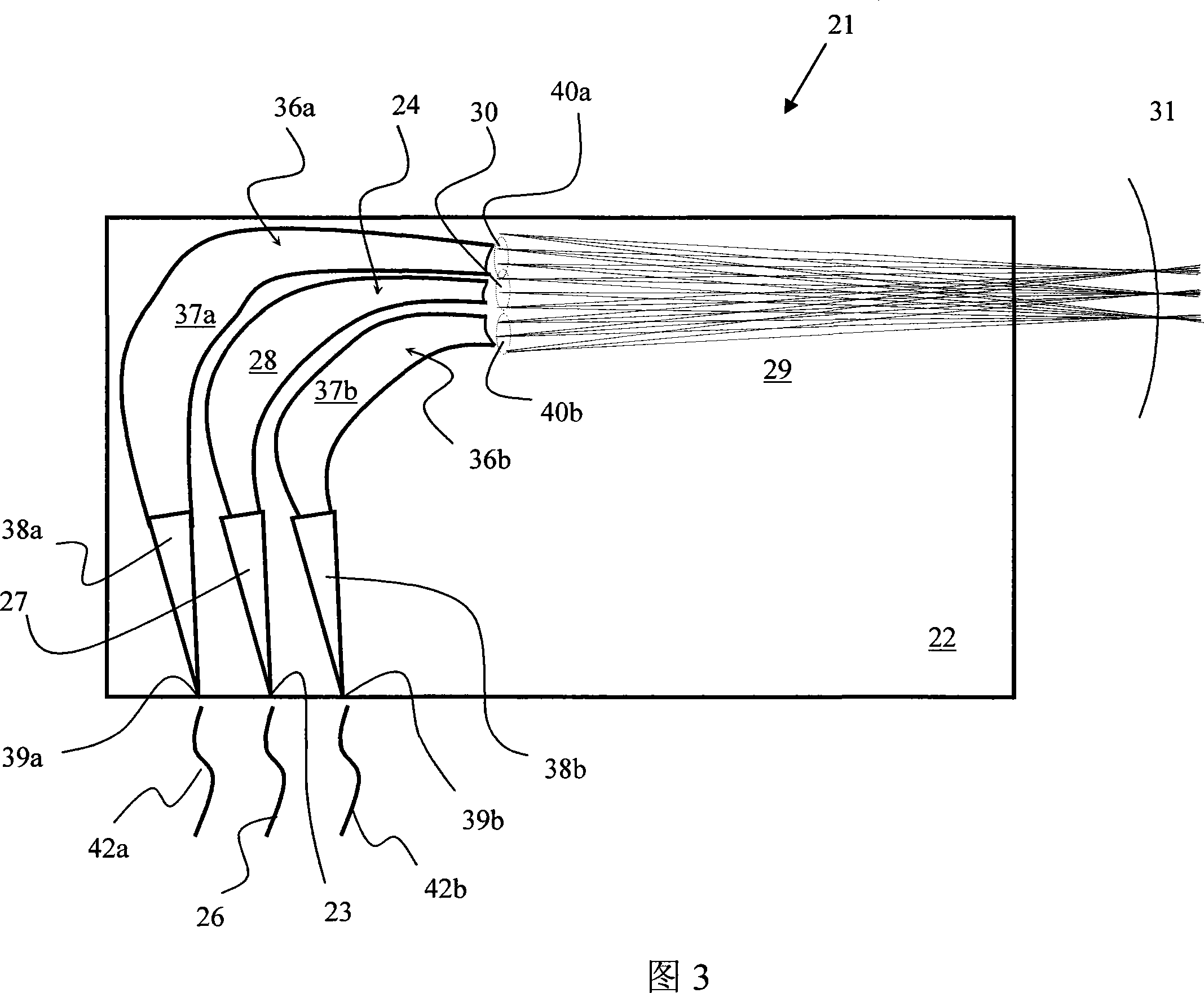
[0040] [35] The present invention extends the concept of a standard arrayed waveguide grating (AWG), which is a Rowland ring converging each wavelength component into the chip, where discrete waveguides are placed that converge each wavelength component in the chip Outside, the MEMS mirror array is then placed at the focal point. Referring to FIG. 3 , the basic device 21 according to the present invention includes a PLC chip 22 with an input port 23 on the edge of the PLC chip 22 for optically coupling a first AWG 24 to an input fiber 26 . The input optical signal including one or more wavelength channels is transmitted from the input optical fiber 26 to the AWG 24 through the input port 23 , and diffracted one-dimensionally to the channel waveguide array 28 in the entrance slab waveguide section 27 . The output of the channel waveguide 28 is connected to an elongated output slab waveguide region 29 along an interface, which is a curved surface, forming a virtual sub-pupil 30 wi...
PUM
Abstract
The present invention extends the concept of a standard array waveguide grating (AWG), which focuses each wavelength component launched via an input AWG to a Rowland circle inside a planar lightwave chip (PLC) where discrete waveguides are located, to one which focuses each wavelength component outside of the PLC chip along a straight line. An array of MEMS mirrors or other redirecting elements is positioned at the focus location for independently redirecting each of the wavelength channels back to any number of selected output AWGs formed on the same PLC chip as the input AWG.
Description
[0001] Cross References to Related Applications [0002] [1] This application claims priority to US Patent Application No. 60 / 821,346, filed August 3, 2006, which is hereby incorporated by reference into this application. technical field [0003] [2] The present invention relates to a wavelength selective switch (WSS), in particular, to a WSS based on planar lightwave loop (PLC) technology. Background technique [0004] [3] Conventional optical wavelength dispersion devices, such as 6,097,859 issued to Solgaard et al. on August 1, 2000, 6,498,872 issued to Bouevitch et al. on December 24, 2002, and Ducellier et al. issued on March 16, 2004 6,707,959 issued to Bouevitch on October 26, 2004, 6,922,239 issued to Solgaard et al., and 7,014,326 issued to Danagher et al. The beam of light is divided into constituent wavelengths and each wavelength or group of wavelengths (which may or may not have been modified) is directed through the device back to a desired output port. Typic...
Claims
Application Information
Patent Timeline
Application Date:The date an application was filed.
Publication Date:The date a patent or application was officially published.
First Publication Date:The earliest publication date of a patent with the same application number.
Issue Date:Publication date of the patent grant document.
PCT Entry Date:The Entry date of PCT National Phase.
Estimated Expiry Date:The statutory expiry date of a patent right according to the Patent Law, and it is the longest term of protection that the patent right can achieve without the termination of the patent right due to other reasons(Term extension factor has been taken into account ).
Invalid Date:Actual expiry date is based on effective date or publication date of legal transaction data of invalid patent.