Electric network electric voltage drop generator

A grid voltage and generator technology, which is applied in the field of grid voltage drop generators, can solve problems such as complex control and expensive voltage drop generators, and achieve the effects of ensuring output waveform quality, high reliability, and improving safety

Inactive Publication Date: 2008-02-06
INST OF ELECTRICAL ENG CHINESE ACAD OF SCI +1
View PDF0 Cites 16 Cited by
  • Summary
  • Abstract
  • Description
  • Claims
  • Application Information

AI Technical Summary

Problems solved by technology

[0003] The purpose of the present invention is to overcome the disadvantages of expensive and complex control of existing voltage drop generators, and propose a new voltage drop generator

Method used


Image

  • Electric network electric voltage drop generator
  • Electric network electric voltage drop generator
  • Electric network electric voltage drop generator

Examples


Embodiment Construction

[0038] The invention will be further described below in conjunction with the accompanying drawings and specific embodiments.

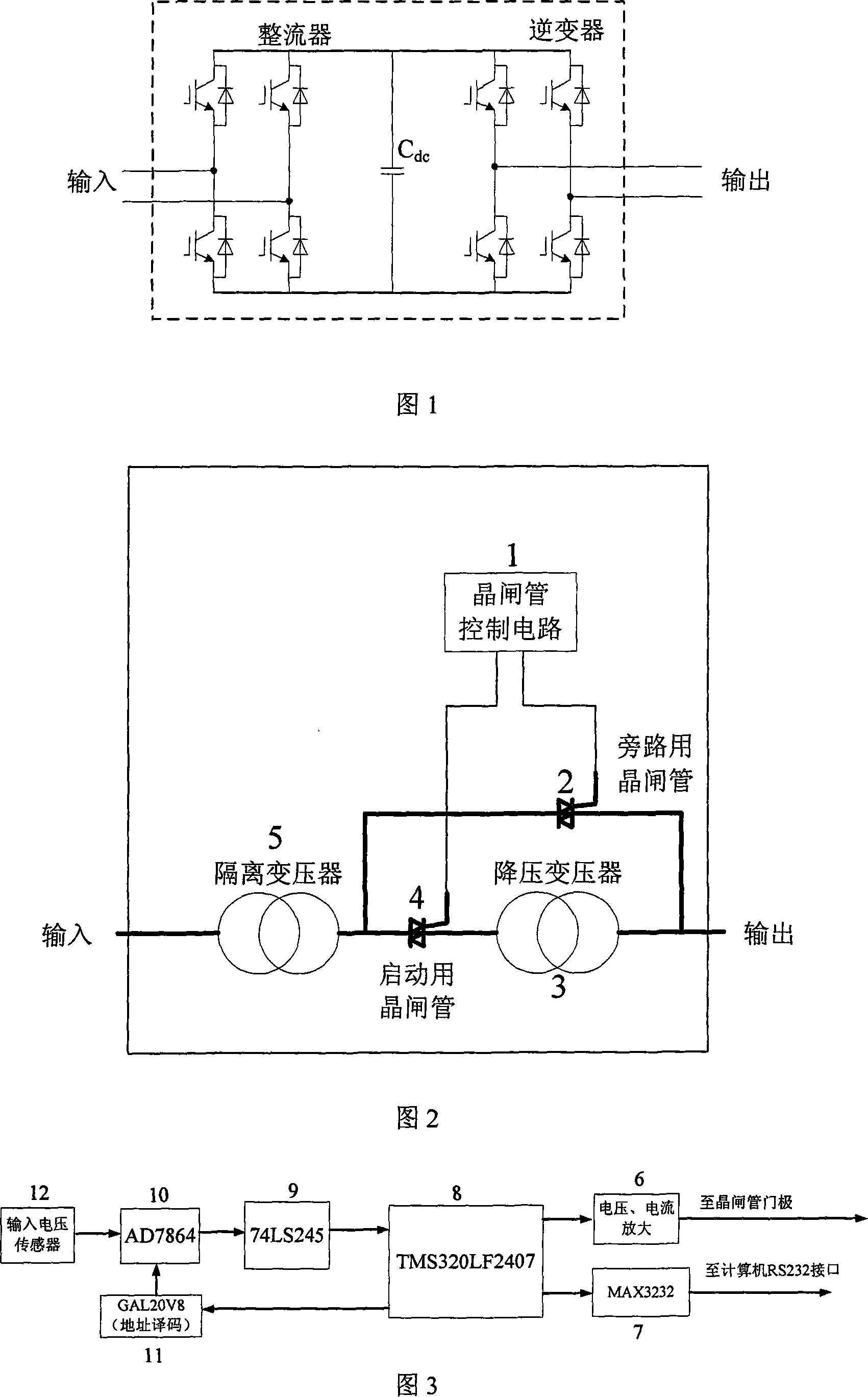
[0039] Fig. 2 is a structural block diagram of the voltage drop generator of the present invention. The present invention comprises a thyristor control circuit 1 , an isolation transformer 5 , a step-down transformer 3 , a bypass thyristor 2 , a starting thyristor 4 and a thyristor drive circuit 6 . The input of the isolation transformer 5 is connected to the input voltage, one end of the main circuit of the starting thyristor 4 is connected to the output of the isolation transformer 5 , and the other end of the main circuit of the starting thyristor 4 is connected to the output of the step-down transformer 3 . One end of the main circuit of the bypass thyristor 2 is connected to the output of the isolation transformer 5, the other end of the main circuit of the bypass thyristor 2 is connected to the input of the step-down transformer 3, and the output...


PUM


Abstract

The present invention relates to a power network voltage drifting-down generator, comprising a thyristor control circuit(1), an isolating transformer(5), a step-down transformer(3), a bypassing thyristor(2), a starting thyristor(4) and a thyristor drive circuit. The thyristor control circuit(1) is used for detecting the input voltage signal, deciding the continuity signals of the reverse parallel connection thyristor. The bypassing thyristor(2) and the starting thyristor(4), sending the actuating signal of the reverse parallel connection thyristor at the zero crossing point of the input signal, the running state of the step-down transformer(3) is controlled through the bypassing thyristor(2) and the starting thyristor(4), changing the value of the input voltage. The present invention is capable of realizing the instant change to the input voltage.

Description

technical field [0001] The invention relates to a power grid voltage drop generating device. Background technique [0002] With the development of power equipment manufacturing level and the improvement of the current digital signal processor performance, the market requires more and more electronic equipment to have a certain ability to resist power grid fluctuations. At present, most of the similar test equipment on the market are made by foreign manufacturers, using large-capacity IGBT full-control power electronic devices, and the price is mostly hundreds of thousands of dollars. The structure is shown in Figure 1. The input voltage is rectified by a large-capacity IBGT full-bridge circuit, and then the DC voltage is inverted and output. By changing the modulation ratio of the output inverter, the instantaneous drop of the output voltage can be realized, and the bidirectional flow of energy can be realized. But the voltage drop generator with this structure uses 8 larg...

Claims


Application Information

Patent Timeline
Patent Type & Authority Applications(China)
IPC IPC(8): H02M5/10H02M5/12
Inventor 李建林梁亮许洪华
Owner INST OF ELECTRICAL ENG CHINESE ACAD OF SCI
Why Eureka
Try Eureka