Narrow slit and large slit combination type microwave plasma reaction cavity

A microwave plasma and reaction chamber technology, applied in the direction of plasma, electrical components, etc., can solve problems such as uneven electric field distribution, and achieve the effect of expanding the distribution range and uniform electric field distribution

Inactive Publication Date: 2008-02-06
TSINGHUA UNIV
View PDF0 Cites 14 Cited by
  • Summary
  • Abstract
  • Description
  • Claims
  • Application Information

AI Technical Summary

Problems solved by technology

[0004] The purpose of the present invention is to overcome the deficiency caused by uneven electric field distribution in the existing slit-type reaction chamber

Method used


Image

  • Narrow slit and large slit combination type microwave plasma reaction cavity
  • Narrow slit and large slit combination type microwave plasma reaction cavity
  • Narrow slit and large slit combination type microwave plasma reaction cavity

Examples


Embodiment Construction

[0020] The present invention will be further described below in conjunction with drawings and embodiments.

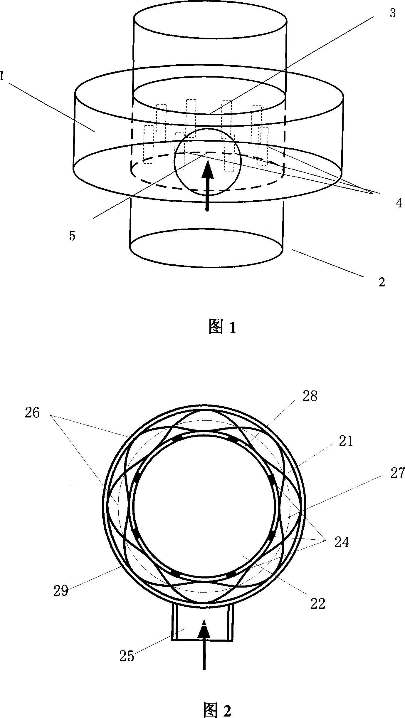
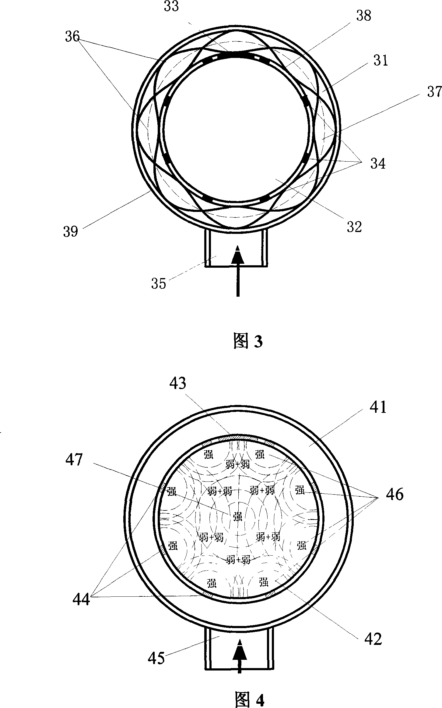
[0021] The structure of an embodiment of the combined slit and large slit microwave plasma reaction chamber proposed by the present invention is shown in FIG. 3 . In this embodiment, the microwave frequency is input at 2.45 GHz, and the reaction chamber 32 is a hollow cylinder placed vertically, and the top and bottom are sealed by detachable flanges (not shown in the figure). In the middle of the cavity, there is a ring waveguide 31 with a rectangular cross section, the inner wall 38 of the ring waveguide coincides with the outer wall of the reaction chamber; the inner wall of the ring waveguide has eight narrow holes corresponding to the number of nodes of the four standing waves in the ring waveguide. slit 34, the position of the slit is just at the node of the standing wave; the outer wall of the ring waveguide 31 has a through hole 35, which is connected to the squ...


PUM


Abstract

The present invention relates to a narrow gap-big gap combined microwave plasma reaction cavity, belonging to microwave plasma excitation technique field. The reaction comprises a vacuum column shape reaction cavity which is arranged vertically, and the upper part and the lower part of the reaction cavity are both sealed by a demountable flange. An annular wave guide with a rectangular-shaped cross section is winded in the middle part of the reaction cavity. The inner wall of the annular wave guide is coincided with the outer wall of the cavity. The inner wall of the annular wave guide is opened with a narrow gap which is corresponding to the wave node quantity of the standing wave inside the annular wave guide. The narrow gap is positioned at the standing wave node. The outer wall of the annular wave guide is opened with a through hole which is used for connecting with the drop-leaf mode wave guide switch or with the coupled antenna. The present invention is characterized in that the inner wall of the annular wave guide is opened with a big gap which is used for forming a symmetric high field inside the reaction cavity, and the high filed is strongest in the middle and then decreased periphery outward gradually; and the high filed is complemented with the electric field formed by the narrow gap to make the electric field is evenly distributed inside the reaction cavity. The present invention has the advantages of effectively improving the distribution of the electric field, producing more even plasma which can also exist inside the middle of the cavity.

Description

technical field [0001] The invention belongs to the technical field of microwave plasma excitation, and in particular relates to the structural design of a reaction chamber for generating large-area microwave plasma. Background technique [0002] Plasma has strong practical value in the fields of new materials, microelectronics and other industries and biological research, especially the way of using microwaves to excite plasma. Compared with other plasma excitation methods, the existence of plasma is larger. The density of charged particles is high, so there is a lot of room for application expansion. In particular, large-area (large-volume) microwave plasma has higher application value in related industries. [0003] Microwave plasma reaction chambers generally use single or mixed microwave modes to generate plasmons inside chambers with different structures. Due to the different structures, the areas of the generated plasma are also different. However, the existing reac...

Claims


Application Information

Patent Timeline
Patent Type & Authority Applications(China)
IPC IPC(8): H05H1/46
Inventor 刘亮张贵新冯剑
Owner TSINGHUA UNIV
Why Eureka
Try Eureka