Liquid tank type cold shock testing device

A technology of thermal shock and test device, applied in measuring devices, instruments, scientific instruments, etc., can solve the problems of bad environment, increased consumption, unfavorable cost, etc., to provide reliability, reduce consumption, and prevent icing phenomenon. Effect

Inactive Publication Date: 2008-02-06
FUTEC
View PDF1 Cites 17 Cited by
  • Summary
  • Abstract
  • Description
  • Claims
  • Application Information

AI Technical Summary

Problems solved by technology

[0011] In the conventional thermal shock test apparatus as described above, when moving between the low-temperature chamber and the high-temperature chamber, once the sample cage is taken out from one chamber, it has to go to the other chamber. The low-temperature liquid and high-temperature liquid attached to the sample cage diffuse during the period, and its consumption increases
Therefore, even if the liquid is replenished at any time, manual labor is required, so long-term continuous testing tends to become difficult.
In addition, these liquids are mostly expensive liquids, and if they are consumed too much, they will become a device that is disadvantageous in cost.
In addition, since the liquid evaporates and diffuses, it is not good in terms of environment

Method used


Image

  • Liquid tank type cold shock testing device
  • Liquid tank type cold shock testing device
  • Liquid tank type cold shock testing device

Examples


Embodiment Construction

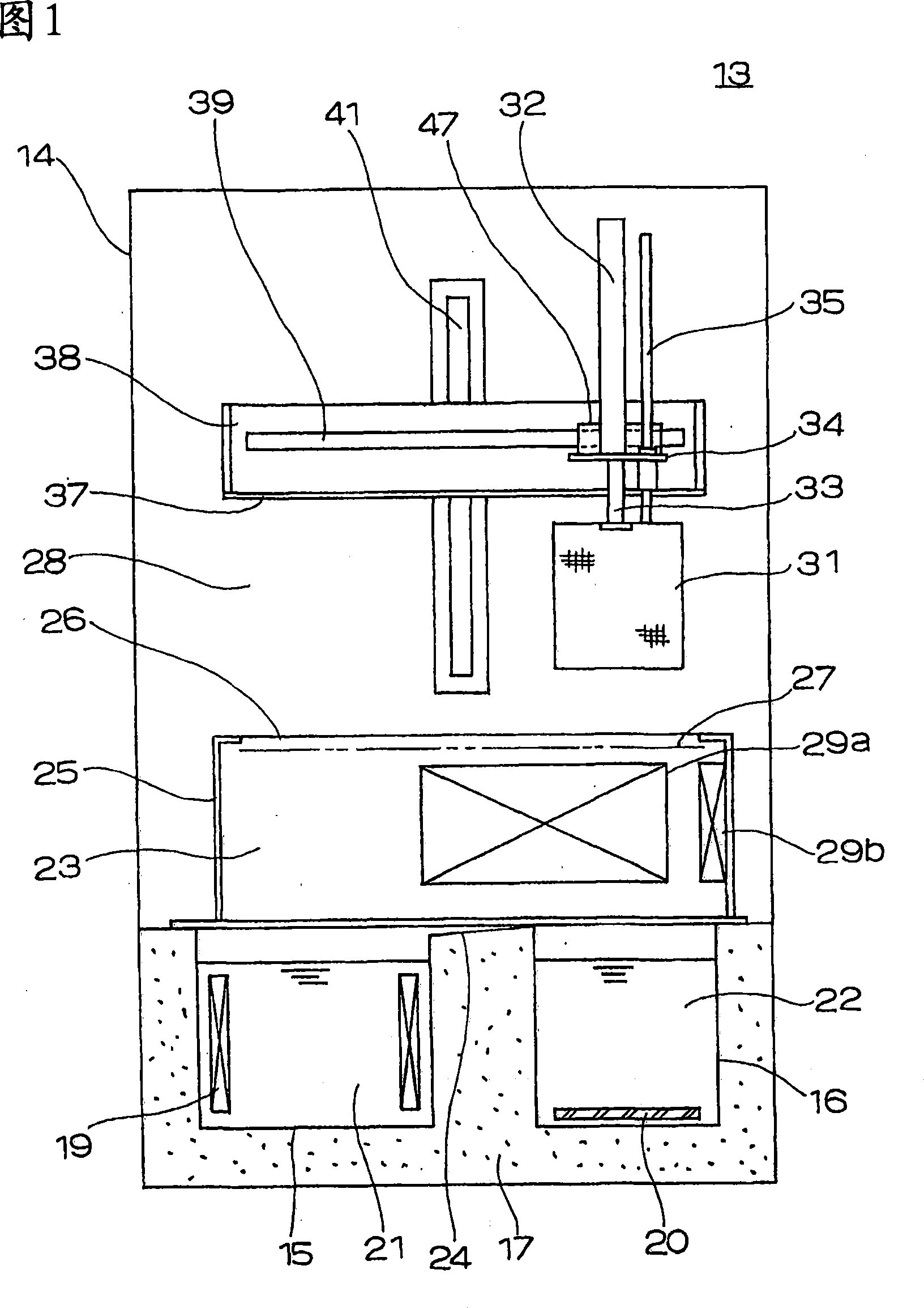
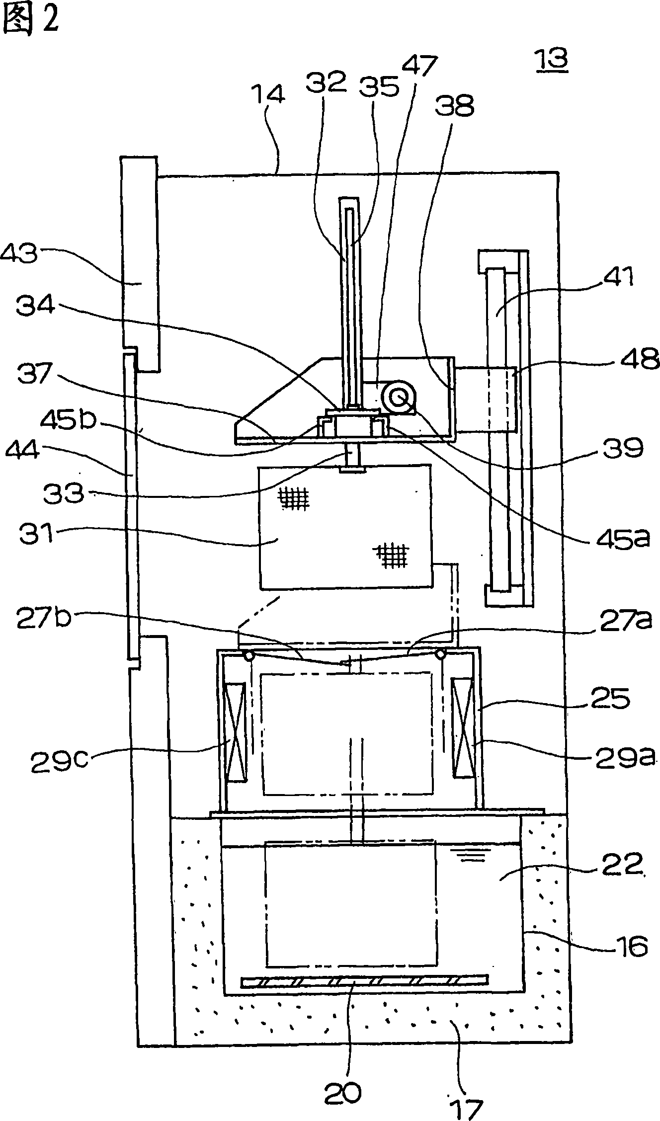
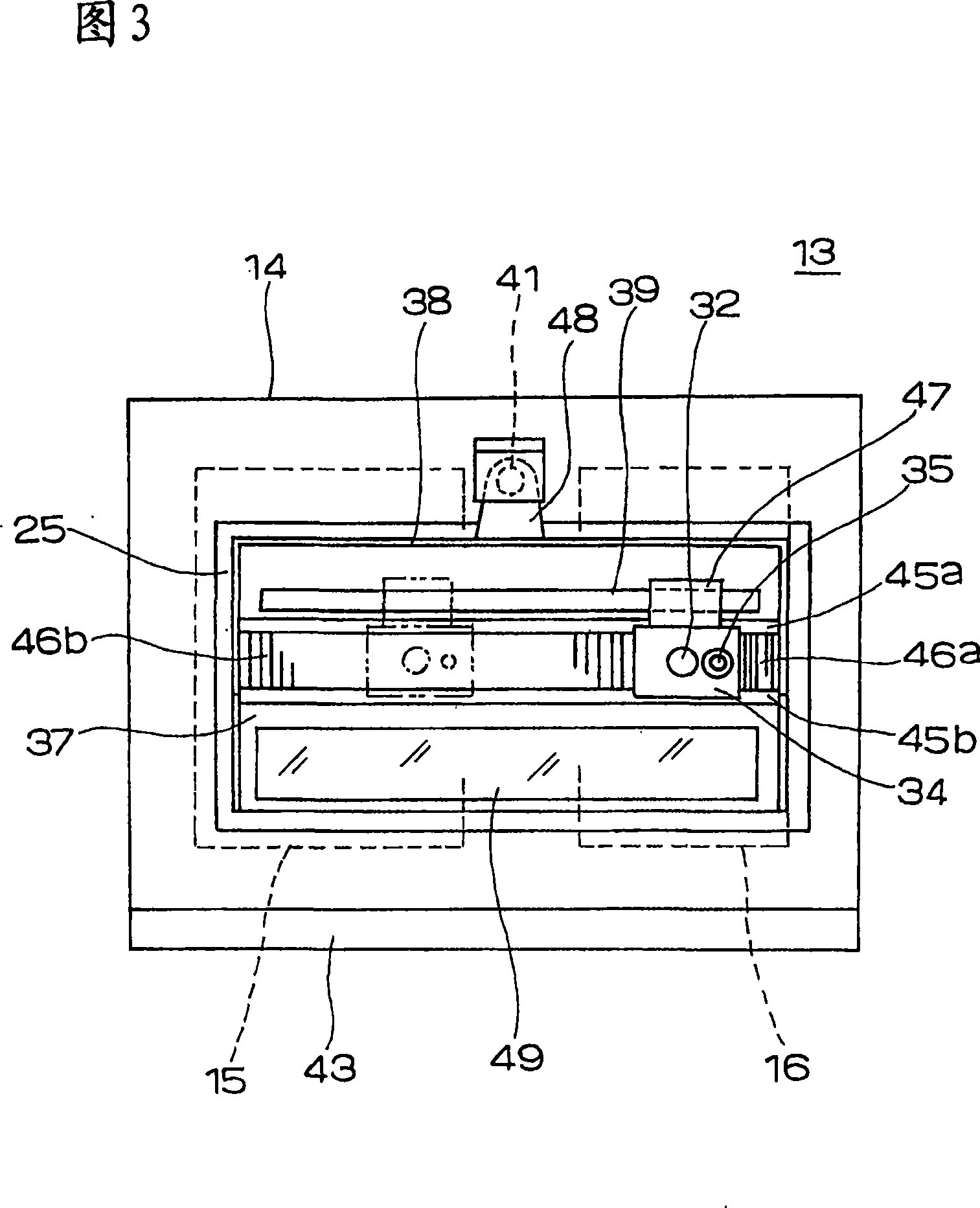
[0041] Fig. 1 is a front view showing a schematic structure of a liquid tank type thermal shock test device according to the first embodiment of the present invention, Fig. 2 is a schematic side view of the test device shown in Fig. 1 , and Fig. 3 is a schematic side view of the test device shown in Fig. 1 . A schematic top view of the test setup.

[0042] Referring to these figures, the liquid tank type thermal shock test device 13 is mainly composed of a rectangular parallelepiped-shaped device main body 14, and the outside of the device main body 14 is substantially sealed. In the lower part of the inside of the device main body 14, a low-temperature tank 15 holding a low-temperature liquid 21 as a first bath liquid and a high-temperature tank 16 holding a high-temperature liquid 22 as a second bath liquid are arranged in a parallel state. The thermal layer 17 is filled and divided. A cooling coil 19 is provided on the side wall of the low-temperature tank 15 , and a heater ...


PUM


Abstract

Under the device main body (14) of the liquid tank type thermal shock test device (13), a low temperature tank (15) and a high temperature tank (16) are arranged side by side with a heat insulating layer (17). Above the low-temperature tank (15) and the high-temperature tank (16), a sealed box (25) is provided, and an opening (26) is formed on the upper surface thereof. Above the box body (25), a sealing cover (37) capable of covering the opening (26) is arranged in a sealed state, and is driven up and down by the cover driving mechanism (41). On the sealing cover (37), a horizontal driving mechanism (39) is arranged, which can drive the fixing plate (34) left and right. On the fixed plate (34), a vertical drive mechanism (32) is installed to freely move the sample cage (31) downward. Accordingly, the sample cage (31) can be repeatedly immersed in the low-temperature tank (15) and the high-temperature tank (16) while the box (25) is sealed by the sealing cover (37).

Description

technical field [0001] The present invention relates to a liquid tank type thermal shock tester, and more particularly to a liquid tank type thermal shock tester for testing the durability, strength, etc., of parts such as small precision instruments or electronic parts based on thermal shock. Background technique [0002] For components such as precision instruments or electronic components, in addition to their general tests, thermal shock tests are performed to confirm durability against thermal influence. Conventionally, this test has been performed in such a way that a sample to be tested is alternately moved between a liquid tank that is liquid in a low-temperature state and a high-temperature liquid tank, and immersed in the test. [0003] Fig. 9 is a front view showing a schematic structure of a conventional tank-type thermal shock test device disclosed in, for example, Japanese Patent Application Laid-Open No. 60-263836. [0004] Referring to the drawings, a liquid...

Claims


Application Information

Patent Timeline
Patent Type & Authority Applications(China)
IPC IPC(8): G01N3/60
CPCG01N3/60G01N3/00G01N3/02
Inventor 山本武靖
Owner FUTEC
Why Eureka
Try Eureka