Auto-feeder

An automatic feeding and sliding block technology, which is applied in the direction of feeding device, positioning device, storage device, etc., can solve the problems of high manufacturing cost, complex structure of automatic feeding machine, high energy consumption, etc.

Inactive Publication Date: 2008-02-13
吕一鸣
View PDF1 Cites 2 Cited by
  • Summary
  • Abstract
  • Description
  • Claims
  • Application Information

AI Technical Summary

Problems solved by technology

[0003] 1. Since the cylinder is used as the power source, the automatic feeder must be equipped with an air compressor and the corresponding air inlet and outlet control mechanism, which makes the automatic feeder

Method used


Image

  • Auto-feeder
  • Auto-feeder
  • Auto-feeder

Examples


Embodiment Construction

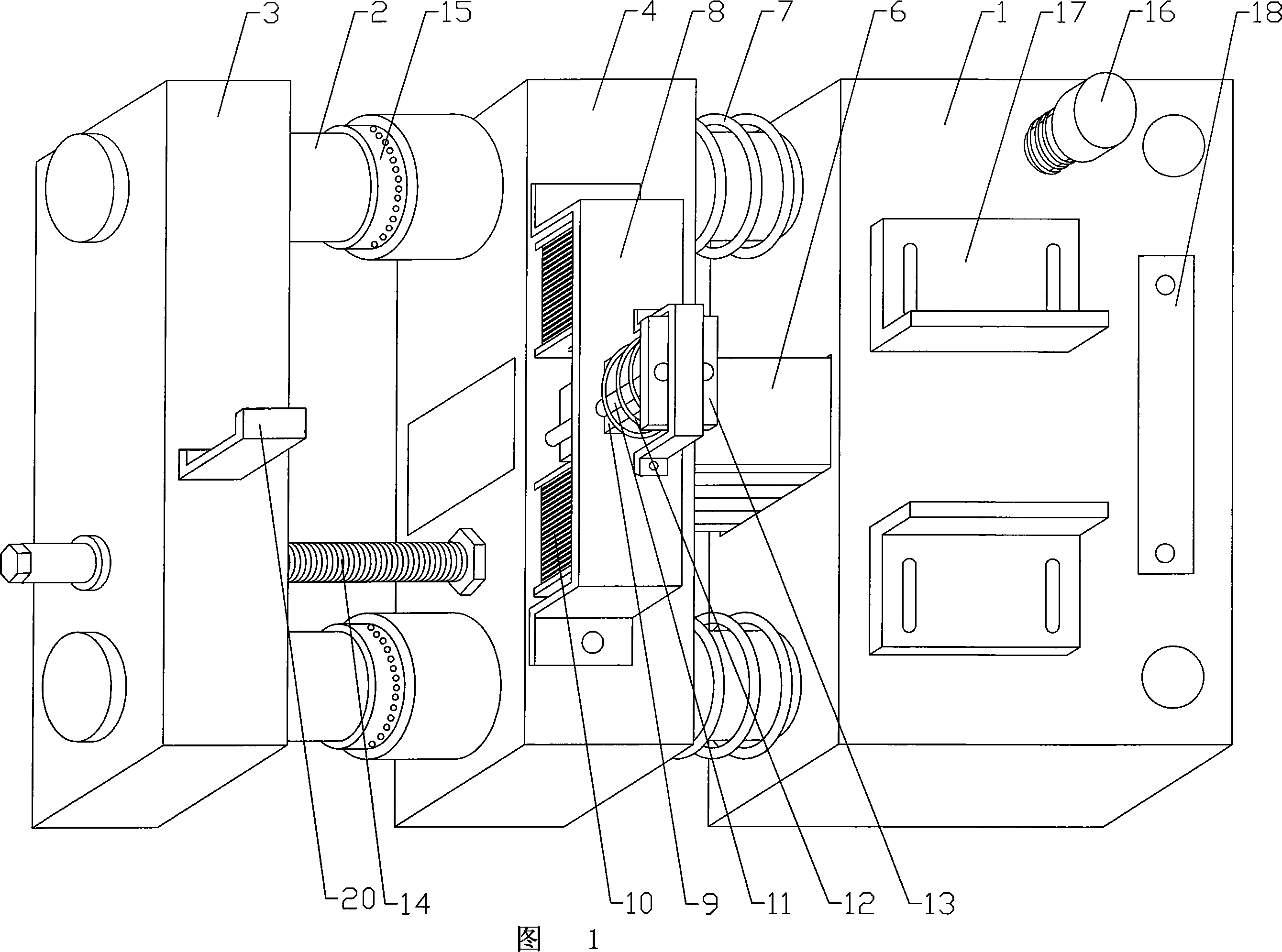
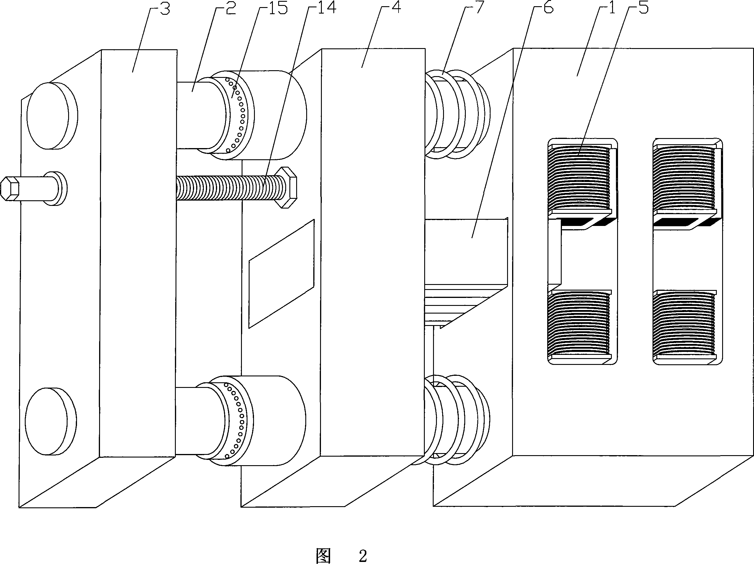
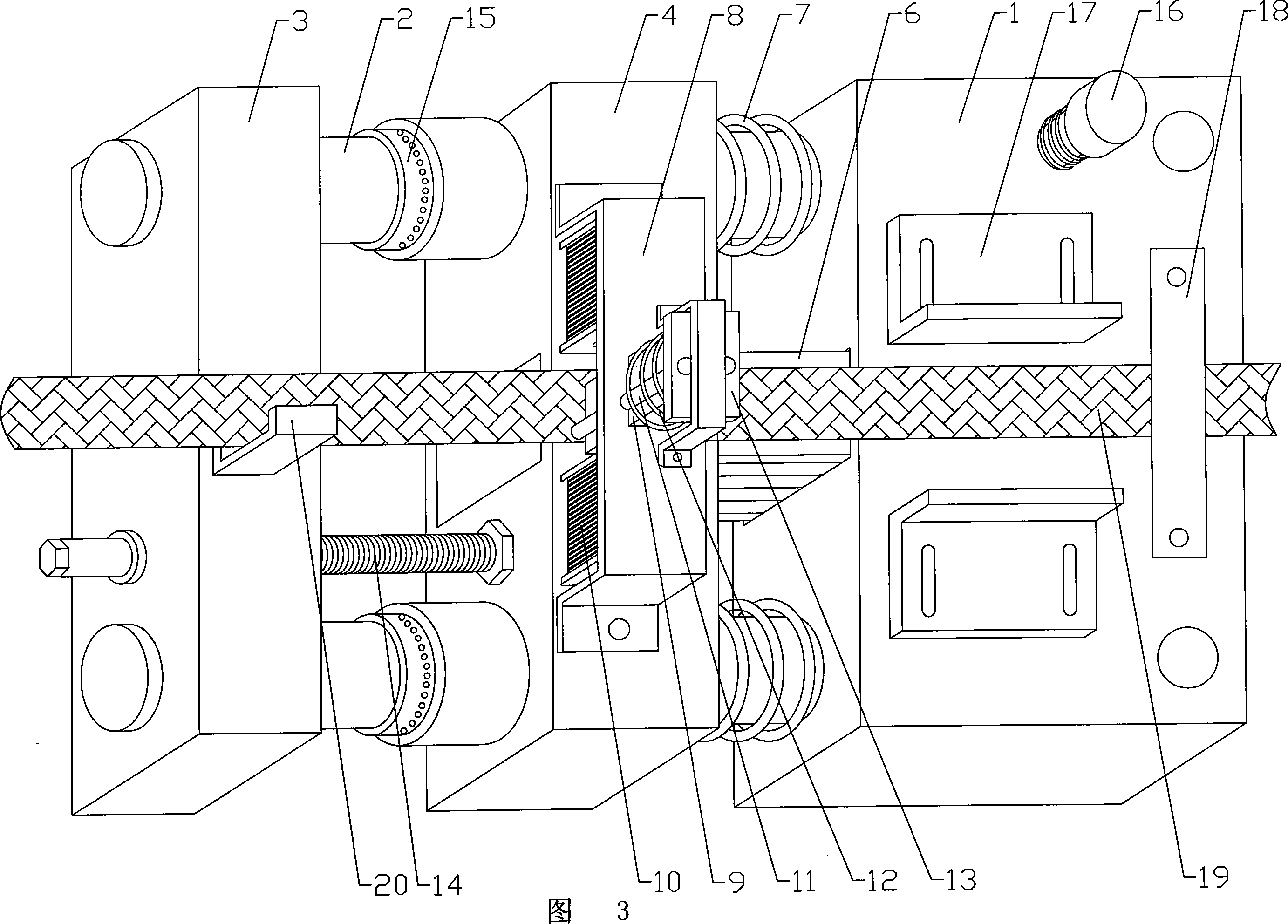
[0020] As shown in Fig. 1, Fig. 2 and Fig. 3: the automatic feeding device of this embodiment includes: a fixed seat 1 fixed on the punch press, one end of the guide rail 2 is connected with the fixed seat, and the other end is fixed on the guide rail frame 3, and the slider 4 A pressing assembly is installed on the top, and the control mechanism controls the slider 4 to move on the guide rail 2. The fixed seat 1 is provided with an electromagnetic coil 5, and the slider 4 is provided with a driving block 6 made of a magnetically conductive material. The control mechanism controls the power on and off of the electromagnetic coil 5, and the driving block 6 drives the slider 4 under the action of the electromagnetic coil. Moving on the guide rail 2, the slider is provided with a return spring 7.

[0021] The pressing assembly includes: a pressing bracket 8 fixed on the slider 4, a pressing electromagnetic coil 10 is arranged on both sides of the pressing slider 9, and the pressi...


PUM


Abstract

An automatic feeding device comprises a fixing base fixed on a punch; one end of a guide way is connected with the fixing base and the other end is fixed on a guide way rack; a slipper block is installed with a pressure feed component and a control mechanism controls the slipper block to move along the guide way. The inside of the fixing base is equipped with an electromagnetic winding and the slipper block is equipped with a driving block made of a magnetic inductive material; the control mechanism controls the power of electromagnetic winding and the driving block drives the slipper block to move with the action of the electromagnetic winding; the slipper block is equipped with a return mechanism. By adopting the electromagnetic winding and driving block, the automatic feeding device can drive the slipper block to move to realize automatic feeding. Moreover, the automatic feeding machine boasts of simple structure, little energy consumption, low manufacture cost and low failure rate.

Description

Technical field: [0001] The invention relates to an automatic feeding device. Background technique: [0002] At present, the automatic feeding device generally uses a cylinder as a power source to drive the automatic feeding device to work. Just disclose a kind of " air automatic feeder " as No. 01277114.7 of Chinese patent. In this technical scheme, the air automatic feeding machine matched with the punching machine has a main body, the main body is connected to one end of the guide post, and the other end of the guide post is connected to the feeding assembly, and the main body is formed with a feeding mechanism, a fixed clamping mechanism, a control mechanism and Transmission mechanism, the transmission mechanism cooperates with the punch cam or mold, the movable clamping mechanism is installed on the guide column, and the movable clamping mechanism is connected with the feeding mechanism, which can realize the purpose of automatic feeding. But there are following defic...

Claims


Application Information

Patent Timeline
IPC IPC(8): B21D43/00B30B15/30
Inventor 吕一鸣
Owner 吕一鸣
Why Eureka
Try Eureka