
Loose fibre dyeing machine

A dyeing machine and loose fiber technology, which is applied in the field of dyeing machines, can solve the problems of shortening the service life of the motor, prone to failure of the motor, and high maintenance rate, and achieves the effect of eliminating axial movement, not easy to break down, and reducing the maintenance rate

Inactive Publication Date: 2008-02-13
郑国洪
View PDF0 Cites 28 Cited by
  • Summary
  • Abstract
  • Description
  • Claims
  • Application Information

AI Technical Summary

Problems solved by technology

In this way, not only the motor is prone to failure and the maintenance rate is high, but also the service life of the motor will be shortened.

Method used


Image

  • Loose fibre dyeing machine
  • Loose fibre dyeing machine

Examples


Embodiment Construction

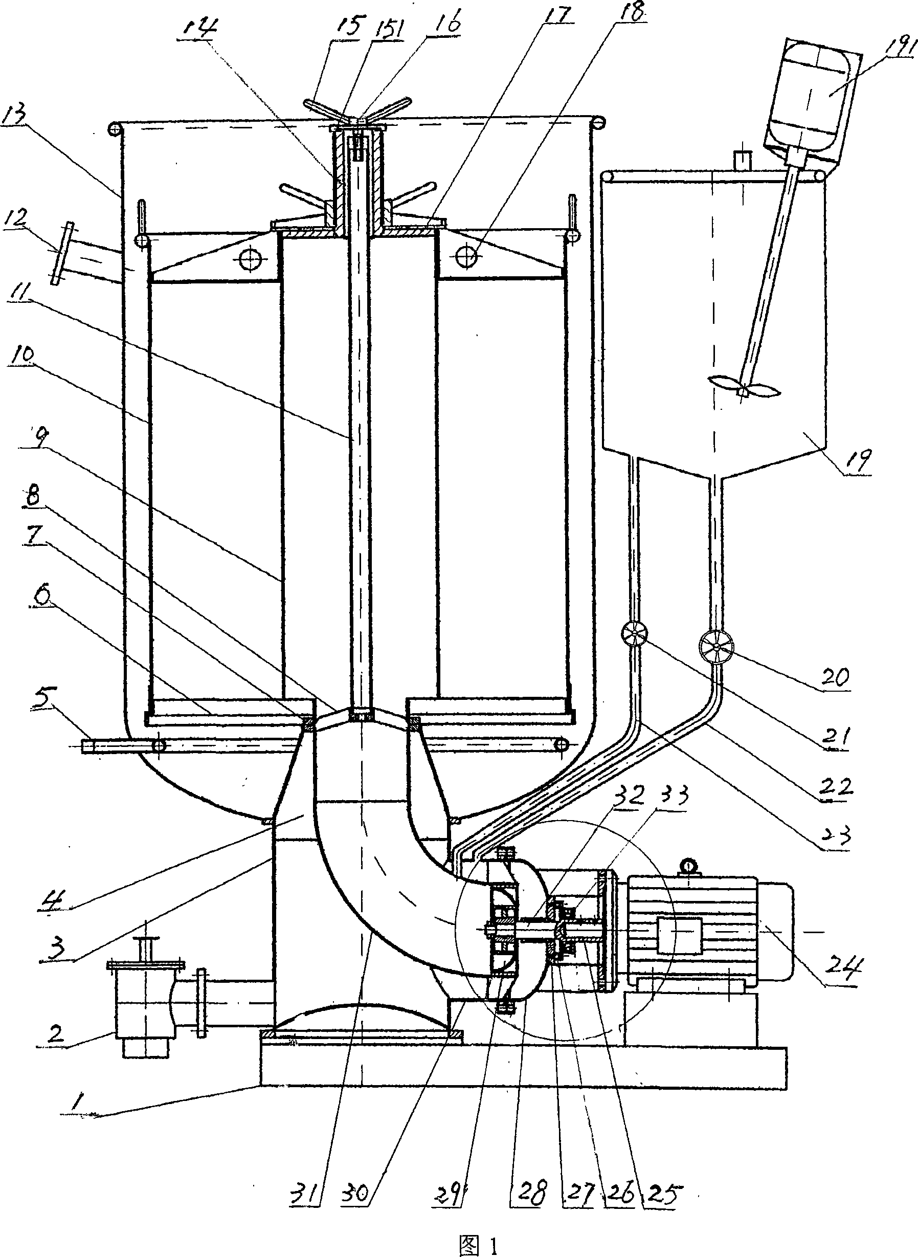
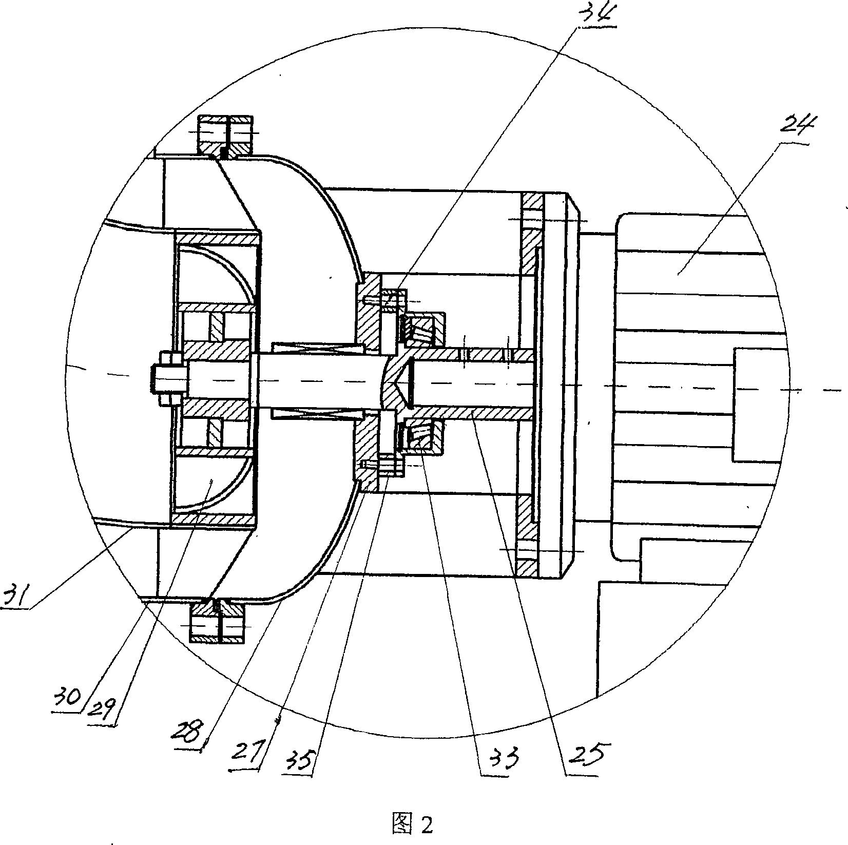
[0011] As shown in Fig. 1 and Fig. 2, the loose fiber dyeing machine of the present invention contains cylinder 13, and this cylinder is cylindrical, and its upper end is open-shaped, and the lower end is connected with arc-shaped cylinder bottom. A water inlet 12 is processed on the top of the cylinder body 13, and a fiber cage 10 is installed in it. Said fiber cage 10 is also a cylinder, and there is a space between the bottom of the cage 6 and the bottom of the cylinder. A heating coil 5 is installed in the space. The steam source and outlet of the same type are connected.

[0012] Both the bottom of the cylinder body 13 and the cage bottom 6 of the fiber cage 10 are processed with a central hole, and a guide cylinder 3 is arranged below the cylinder body 13 . The lower end of the guide cylinder 3 is closed and fixed on the machine base 1, and its upper end is welded circumferentially around the central hole at the bottom of the cylinder body 13. Four connecting ribs 4 are...


PUM


Abstract

The invention discloses a loose fiber dyeing machine, which contains a cylinder. The cylinder is provided with a fiber cage and a central spray pipe from in to out. A heating coil is arranged below the cage bottom. The bottom of the cylinder is provided with a motor and an impeller and one side of the cylinder is provided with a preplasticator cylinder; the preplasticator cylinder is communicated with the inner cavity of the cylinder. The invention is characterized that the cylinder bottom is provided with a central hole, and a guide cylinder is arranged below the central hole. The upper end of the guide cylinder is communicated with the inner cavity of the cylinder; a guide flow cylinder is arranged in the guide cylinder; the side wall is provided with a through hole, and a transverse short cylinder is connected to the outside of the through hole. The opening of the transverse short cylinder is provided with a seal cover. The guide flow cylinder is a bend cylinder, with the upper end subsequently inserted into the cylinder and the central spray pipe, and the lower end arranged in the transverse short cylinder and some distance away from the seal cover, so as to communicate the guide cylinder and the guide flow cylinder. The impeller is positioned in a transverse section of the guide flow cylinder, with a wheel shaft extending out of the seal cover and connected with an output shaft of the motor. The loose fiber dyeing machine can reduce the manufacturing cost, extend the service life of the motor, and is applicable in dyeing of all loose fiber.

Description

technical field [0001] The invention relates to a dyeing machine. Specifically, loose fiber dyeing machines are used to dye various natural or artificial loose fibers such as cotton, acrylic, wool and cashmere, and can also be used for refining, bleaching and softening of these loose fibers. Background technique [0002] At present, in the printing and dyeing industry, the bulk fiber dyeing machines used to dye various natural or artificial bulk fibers such as cotton, acrylic, wool and cashmere are traditional dyeing machines. This traditional dyeing machine contains a cylinder body, a fiber cage is arranged in the cylinder body, a central spray pipe is installed in the fiber cage, and the lower end of the central spray pipe is fixedly connected with the cage bottom of the fiber cage. A heating coil is installed under the bottom of the cage, and one end of the heating coil protrudes from the cylinder body and communicates with the steam source. A motor and a water pump are...

Claims


Application Information

Patent Timeline
IPC IPC(8): D06B1/00D06B5/14D06B23/00
CPCD06B5/16
Inventor 郑国洪王建
Owner 郑国洪
Learn More