Shock absorption wall and construction method thereof

A technology for walls and corners, applied in the field of shock-absorbing walls and their construction, can solve the problems of large foundation reaction force, hindering building separation, large economic investment, etc., and achieve the effect of reducing deformation

Inactive Publication Date: 2008-02-13
ARCHITECTURAL DESIGN RES INST OF GUANGDONG PROVINCE
View PDF0 Cites 24 Cited by
  • Summary
  • Abstract
  • Description
  • Claims
  • Application Information

AI Technical Summary

Problems solved by technology

Generally speaking, the foundation reaction force required by buildings is relatively large, especially for large-span and large cantilever structures and suspension space structures, if seismic isolation equipment is installed on the foundation, it will inevitably put forward higher requirements for the bearing capacity and stiffness of the equipment. , requires a large economic investment, and the base isolation can only reduce the deformation under the horizontal earthquake, and has little effect on the response of the structure under the vertical earthquake, nor can it completely eliminate the risk of resonance; if between components or Install tuned mass dampers under the floor slabs, those damping devices like supports will seriously affect the aesthetics of the building, and even hinder the division of the building
[0004] How to simply use the conditions of the building structure itself, by adding a small amount of additional components, can be used as a part of the building structure, and at the same time play a role in damping the structure itself, such a shock-absorbing wall has not yet appeared

Method used


Image

  • Shock absorption wall and construction method thereof
  • Shock absorption wall and construction method thereof
  • Shock absorption wall and construction method thereof

Examples


Embodiment 1

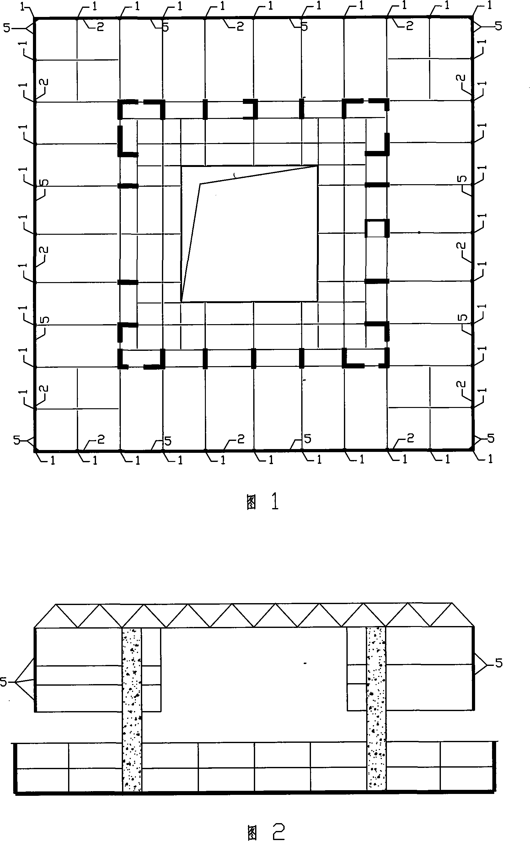
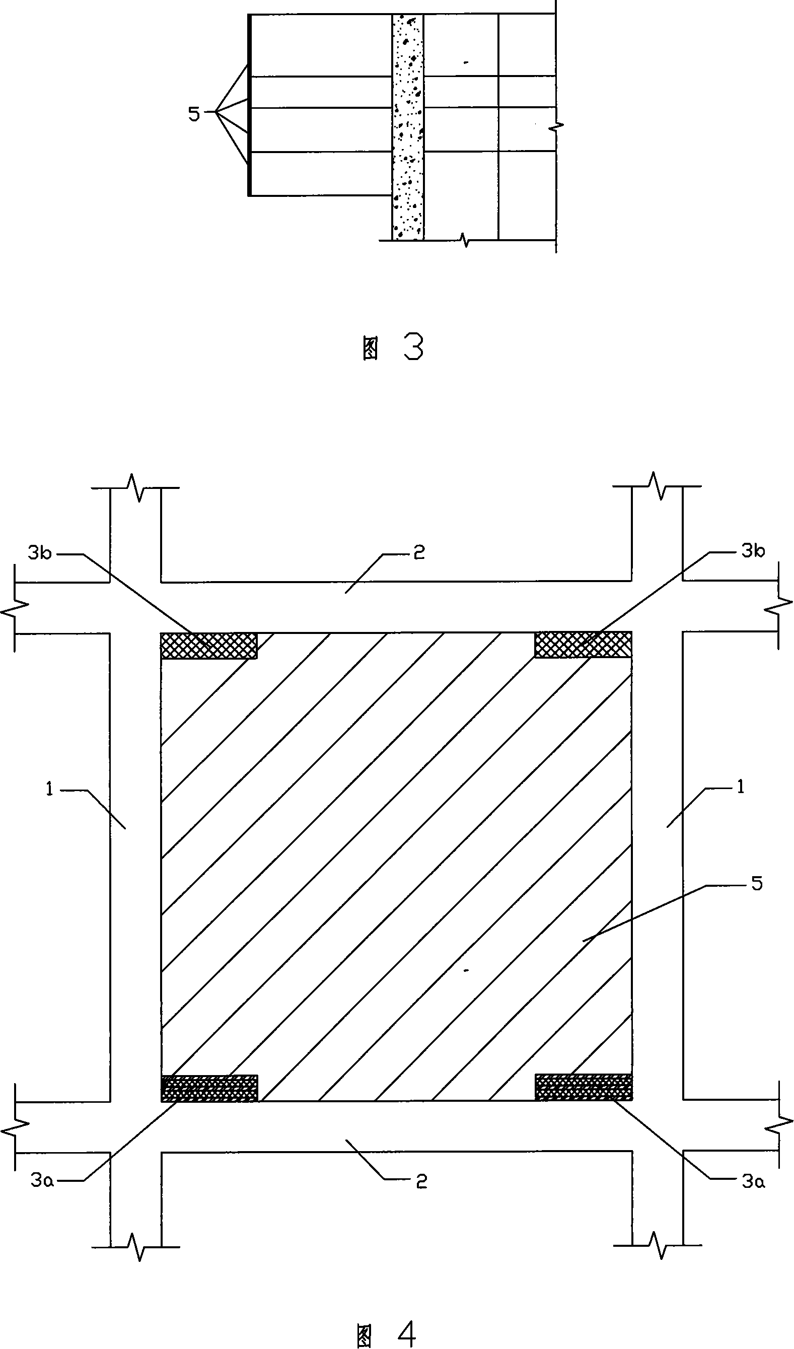
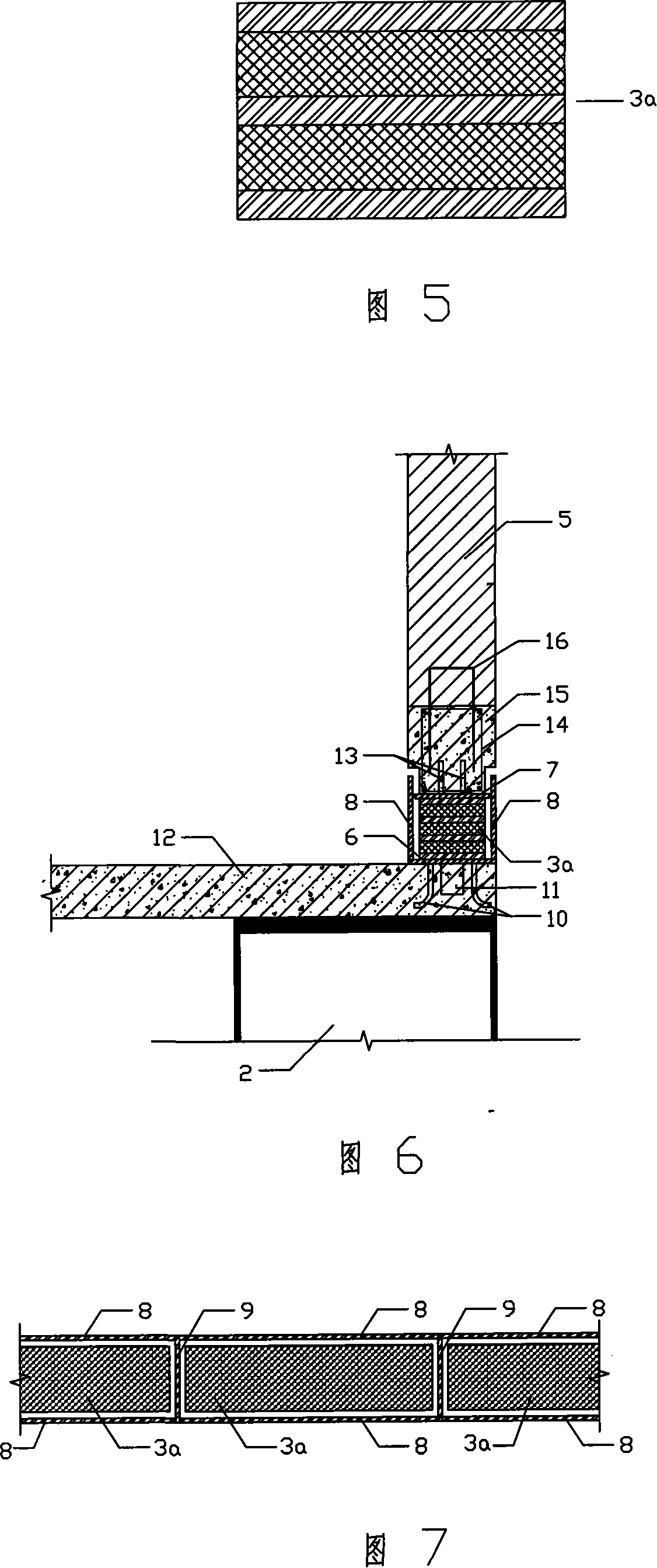
[0068] A kind of shock-absorbing wall as shown in Fig. 1~9, this shock-absorbing wall can be used in the large cantilever building structure or in the suspended space structure, this shock-absorbing wall comprises wall body 5, wall body frame and shock-absorbing device, shock-absorbing The vibration device is a pair of rubber pads arranged symmetrically around the center surface of the wall body. The rubber pads are block-shaped and set at the corners of the wall body 5. The walls 5 are surrounded by structural beams formed by pouring concrete. 15, 22, the structural beam constitutes the peripheral frame of the wall, the rubber pad is in contact with the structural beam of the wall 5, and the rubber pad includes a pair of horizontal rubber pads 3a symmetrically arranged at the lower corner and symmetrically arranged on the upper A pair of horizontal rubber pads 3b at the corner, among which a pair of horizontal rubber pads 3a arranged at the lower corner are interlayer rubber p...

Embodiment 2

[0080] Different from Embodiment 1, the rubber pad of this embodiment also includes a pair of vertical rubber pads 4a symmetrically arranged at the upper corner and a pair of vertical rubber pads 4b symmetrically arranged at the lower corner. It is a clean rubber pad without compression stiffness, as shown in Figures 10-12, the vertical rubber pads 4a, 4b and the horizontal rubber pads 3a, 3b are perpendicular to each other to form a right-angled structure, and the vertical rubber pads The pad also has the same peripheral device as the horizontal rubber pad arranged at the upper corner in Embodiment 1, and the peripheral device consists of an outer steel plate 17, an inner steel plate 18 and a middle partition 19 between the outer steel plate and the inner steel plate. Form a plurality of compartments for accommodating vertical rubber pads 4a, 4b, the horizontal planes of the vertical rubber pads 4a, 4b are respectively parallel to the inner and outer steel plates and the middl...

Embodiment 3

[0085] A kind of shock-absorbing wall as shown in Fig. 13~16, this shock-absorbing wall can be used in the large-span building structure, the shock-absorbing device in this shock-absorbing wall is all the same as the shock-absorbing device in embodiment one, and embodiment One difference is that the beam of the wall frame is a frame beam 24, the column of the wall frame is a structural column 23, and the structural column 23 and the frame beam 24 are all reinforced concrete structures, and the remaining structural members and structures The connection relationship between the components is the same as the structure in Embodiment 1, and will not be repeated here.

[0086] When the shock-absorbing wall of the present invention is used in a large-span structure, if the wall frame adopts a steel structure, its construction method is the same as that of the above-mentioned shock-absorbing wall for a large cantilever. For reinforced concrete structures, the construction method adopt...


PUM


Abstract

The invention discloses a vibration-absorbing wall which includes a wall body and a wall frame; the wall frame consists of posts and beams. The vibration-absorbing wall is characterized in that the wall body is provided with vibration-absorbing devices; the vibration-absorbing devices are rubber cushions, which are symmetrically arranged at wall angles of the wall body; the rubber cushions are in block shape, and include a pair of horizontal cushions symmetrically arranged at the lower wall angles and a pair of horizontal cushions symmetrically arranged at the upper wall angles; wherein, the horizontal rubber cushions at the lower wall angles can adopt laminated rubber cushions combined with rubber and steel plates as vibration-absorbing parts for reducing vertical deformation; while the horizontal rubber cushions at the upper wall angles are pure rubber cushions without compressive rigidity. The vibration-absorbing wall of the invention can reduce the horizontal and vertical deformation of the wall body and has quite good vibration-absorbing and preventing effect with current building wall body and through adding the vibration-absorbing devices, with simple structure and is convenient in construction. Meanwhile, the invention discloses the construction method of the vibration-absorbing wall.

Description

technical field [0001] The invention relates to a shock-absorbing wall with a shock-absorbing function in a building structure and a construction method thereof, in particular to a shock-absorbing wall applicable to a large-span or large-cantilever building structure and a construction method thereof. There is a shock absorbing device, which can reduce the horizontal deformation and vertical deformation of the wall, so as to achieve the effect of shock absorption. Background technique [0002] With the increase in the height of high-rise buildings, the diversification of building functions, the demand for beautiful building shapes, the comfort of building space and use, and the improvement of integration with urban planning, building shapes are becoming more and more novel and unique, especially the atrium space The emergence of and changes in the bottom space have put forward higher requirements for the seismic performance of building structures, especially in large-span an...

Claims


Application Information

Patent Timeline
Patent Type & Authority Applications(China)
IPC IPC(8): E04B1/98E04B2/56E04H9/02
Inventor 陈星李娜王华林何锦超朱耀洲蔡赞华徐静郭伟杰钟云开梁哥怡王建忠王镇平
Owner ARCHITECTURAL DESIGN RES INST OF GUANGDONG PROVINCE
Why Eureka
Try Eureka